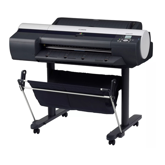
Canon iPF6100 Service Manual
Hide thumbs
Also See for iPF6100:
- User manual (736 pages) ,
- Service manual (692 pages) ,
- Brochure & specs (8 pages)
Summary of Contents for Canon iPF6100
- Page 1 SERVICE MANUAL DU7-1226-000 JULY 2007 REV. 0 COPYRIGHT 2006 CANON INC. CANON imagePROGRAF iPF6100 REV. 0 PRINTED IN U.S.A. fineline6...
- Page 2 Contents Contents Chapter 1 PRODUCT DESCRIPTION 1.1 Product Overview....................1 1.1.1 Product Overview....................... 1 1.2 Features......................1 1.2.1 Features........................1 1.2.2 Printhead ........................1 1.2.3 Ink Tank ........................1 1.2.4 Cutter ........................... 1 1.2.5 Roll Feed Unit ......................1 1.2.6 Stand..........................1 1.2.7 IEEE1394 (FireWire) Board..................
-
Page 3: Chapter 2 Technical Reference
Contents 1.7.2.3 Handling the Printer ......................1-58 1.7.3 Precautions When Servicing Printer ..............1-62 1.7.3.1 Notes on the Data Stored in the Printer ................. 1-62 1.7.3.2 Confirming the Firmware Version ..................1-62 1.7.3.3 Precautions against Static Electricity ................1-62 1.7.3.4 Precautions for Disassembly/Reassembly..............1-62 1.7.3.5 Self-diagnostic Feature ..................... - Page 4 Contents 2.4.2.1 Main controller components....................2-56 2.4.3 Carriage Relay PCB ....................2-58 2.4.3.1 Carriage PCB components ....................2-58 2.4.4 Motor Driver ......................2-59 2.4.4.1 Roll feed unit PCB components ..................2-59 2.4.5 Maintenance Cartridge Relay PCB ...............2-59 2.4.5.1 Maintenance cartridge relay PCB components ............. 2-59 2.4.6 Power Supply ......................2-60 2.4.6.1 Power supply block diagram.....................
-
Page 5: Table Of Contents
Contents 4.3.4 External Covers ......................4-3 4.3.5 Driving Unit....................... 4-19 4.3.6 Cutter......................... 4-20 4.3.7 Carriage Unit ......................4-23 4.3.8 Feeder Unit....................... 4-34 4.3.9 Roll Feed Unit ......................4-38 4.3.10 Purge Unit....................... 4-42 4.3.11 Waste Ink Collection Unit..................4-45 4.3.12 Ink Tank Unit......................4-50 4.3.13 Head Management Sensor.................. - Page 6 Contents 6.3.1 Firmware Update Tool..................... 6-36 6.4 Service Tools ....................6-37 6.4.1 Tool List ........................6-37 Chapter 7 SERVICE MODE 7.1 Service Mode ..................... 7-1 7.1.1 Service Mode Operation ................... 7-1 7.1.2 Map of the Service Mode..................7-2 7.1.3 Details of Service Mode ..................7-12 7.1.4 Sample Printout......................
- Page 7 Chapter 4 DISASSEMBLY/REASSEMBLY fineline6...
-
Page 8: Ink Tank
Contents Contents 4.1 Service Parts...................... 4-1 4.1.1 Service Parts....................... 4-1 4.2 Disassembly/Reassembly................4-1 4.2.1 Disassembly/Reassembly..................4-1 4.3 Points to Note on Disassembly and Reassembly ........4-1 4.3.1 Note on assemblies (or units) prohibited from disassembly ....... 4-1 4.3.2 Moving the carriage manually .................. 4-2 4.3.3 Units requiring draining of ink................... - Page 9 Chapter 4 4.1 Service Parts 4.1.1 Service Parts he service parts indicated below require careful handling. Keep all packages with the warning not to turn over. ay careful attention to all individually packaged service part (carriage unit, purge unit, ink tank unit, and other arts) boxes marked "This side up"...
-
Page 10: Moving The Carriage Manually
Chapter 4 4.3.2 Moving the carriage manually Move the carriage as required during disassembly/reassembly to prevent the carriage form contacting the par to be removed. The carriage does not move when capped. When uncapping moving the carriage, refer to the procedures DISASSEMBLY/REASSEMBLY>Points to Note on Disassembly and Reassembly>Opening the Cap/Movin the Wiper Unit. -
Page 11: Troubleshooting
Chapter 6 TROUBLESHOOTING fineline6... -
Page 12: Firmware
Contents Contents 6.1 Troubleshooting....................6-1 6.1.1 Outline ..........................6-1 6.1.1.1 Outline of Troubleshooting....................6-1 6.2 Location of Connectors and Pin Arrangement ..........6-2 6.2.1 Main controller PCB....................6-2 6.2.2 Carriage PCB......................6-20 6.2.3 Power supply ......................6-33 6.2.4 Roll feed unit PCB....................6-34 6.3 Version Up...................... -
Page 13: Outline
Chapter 6 6.1 Troubleshooting 6.1.1 Outline 6.1.1.1 Outline of Troubleshooting 1. Outline Troubles subject to troubleshooting are classified into those shown on the display (warning, error, and service call) and those not shown on the display. 2. Precautions for Troubleshooting 1) Check the environmental conditions and the media used for printing. -
Page 14: Location Of Connectors And Pin Arrangement
Chapter 6 6 2 Location of Connectors and Pin Arrangement 1 Main controller PCB J2601 J401 J3411 J3402 J3101 J3701 J3801 J1101 J1801 J3401 J2801 J3211 J3501 J3601 J3911 J3202 3 03 J3301 J2703 J1001 J2511 J2512 J1201 J3011 F-6-1 T-6-1 J1001 (USB) Signal name... - Page 15 PARTS CATALOG DU7-3199-000 JULY 2007 REV. 0 COPYRIGHT ©2006 CANON INC. CANON imagePROGRAF iPF6100 REV. 0 PRINTED IN U.S.A. fineline6...
- Page 16 Whenever ordering parts, consult this Parts Catalog for all of the information pertaining to each item. Be sure to include, in the Parts Request, the full item description, the item part number, and the quantity. COPYRIGHT (C) 1999 CANON INC. Use of this manual should be strictly supervised to avoid disclosure of confidential information.
-
Page 17: Carriage Unit
Contents NUMERICAL INDEX iPF6100(Numerical Index) ..............1-1 iPF6100(Parts Catalog) PRINTER & ACCESSORIES ..........2-1 ROLL UNIT ................2-3 COVERS (1) ................2-6 COVERS (2) ................2-8 ELECTRICAL PART ............2-10 PURGE UNIT ...............2-12 CUTTER UNIT ..............2-14 INK SUPPLY UNIT ..............2-16 LINEAR SCALE & LIFT DRIVE UNIT ........2-18 CARRIAGE UNIT ..............2-20... - Page 18 CANON imagePROGRAF iPF6100 service manual CANON imagePROGRAF iPF6100 service manual CANON imagePROGRAF iPF6100 service manual CANON imagePROGRAF iPF6100 service manual CANON imagePROGRAF iPF6100 service manual CANON imagePROGRAF iPF6100 service manual CANON imagePROGRAF iPF6100 service manual CANON imagePROGRAF iPF6100 service manual...


