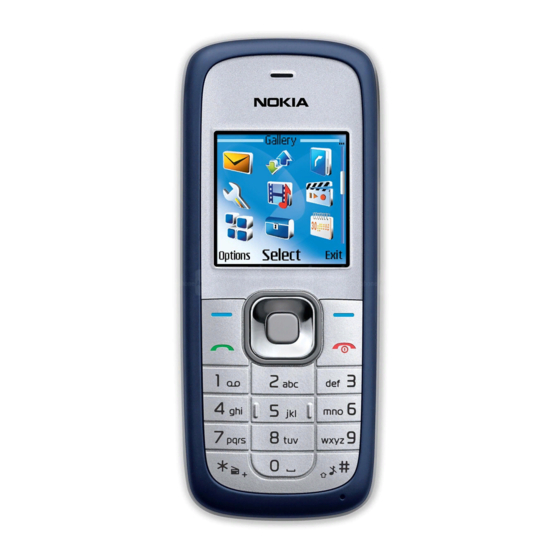
Nokia 1508 Manual
Rf description and troubleshooting
Hide thumbs
Also See for 1508:
- User manual (129 pages) ,
- Manual (34 pages) ,
- Disassembly and assembly (6 pages)
Summary of Contents for Nokia 1508
- Page 1 1508(RM-388) RF Description and Troubleshooting Nokia Customer Care Nokia Customer Care 1508 (RM-338) Mobile Terminal RF Description and Troubleshooting Issue 1 Copyright © 2008 Nokia, All rights reserved...
- Page 2 1508(RM-388) RF Description and Troubleshooting Nokia Customer Care Contents 1508 RF troubleshooting Issue 1 Copyright © 2008 Nokia, All rights reserved...
-
Page 3: Table Of Contents
Tx Path Troubleshooting..................10 RxTroubleshooting....................11 Rx System Block Diagram..................11 Rx Introduction....................11 AMS Setup for Rx Troubleshooting..............11 Cell Receiver Check from RF to IQ..............12 Receiver DC Test Points..................14 Receiver RF Test Points..................14 Rx Path Troubleshooting..................16 Issue 1 Copyright © 2008 Nokia, All rights reserved... -
Page 4: Component Layout
1508(RM-388) RF Description and Troubleshooting Nokia Customer Care Component Layout Figure 1 and Figure 2 show the main components of the 1508 mobile terminal. Figure 1: Component layout (Top) Issue 1 Copyright © 2008 Nokia, All rights reserved... - Page 5 1508(RM-388) RF Description and Troubleshooting Nokia Customer Care Figure 2: Component layout (Bottom) Issue 1 Copyright © 2008 Nokia, All rights reserved...
-
Page 6: Txtroubleshooting
1. Connect RF connector to a CMU200 or 8960. 2. Connect the PWB to a PC via the Module Jig, and connect a power supply. 3. Open AMS Tools software and select RF Tool. Issue 1 Copyright © 2008 Nokia, All rights reserved... - Page 7 8. Choose DSPM TX AGC Config. Set Hyst State “medium gain”, Power (dBm) “24dBm” then send 9. Choose CP AUX ADC Get. Set TX PCG Sync “off” then send to get Power detector ADC value. Figure 5: FTM dialog box Issue 1 Copyright © 2008 Nokia, All rights reserved...
-
Page 8: Tx Dc Test Points
3.08V for Lock, 0 V for unlock TX_AGC 1.92V for 5dB, 2.16V for 15dB, 2.4V for 25dB. Tx IQ in 0.8 V With oscilloscope: 500 mV p-p Tx_on 2.8 V Table 1: Tx DC Test Points Issue 1 Copyright © 2008 Nokia, All rights reserved... -
Page 9: Tx Dc Test Points
Value Tx saw output about 4dBm PA input about 2dBm PA output about 28dBm TCXO_RF about 0dBm RF connector about 24dBm Coupler output about 26dBm Table 2: Tx RF Test Points Issue 1 Copyright © 2008 Nokia, All rights reserved... -
Page 10: Tx Path Troubleshooting
If RF antenna feed point pad obstructed, clean the pad, Reheat the solder joints of L112, L123 connect system simulator to the Check antenna module MS antenna, is it OK? Tx troubleshooting finished Issue 1 Copyright © 2008 Nokia, All rights reserved... -
Page 11: Rxtroubleshooting
2. Connect the PWB to a PC via the Module Jig, and connect a power supply. 3. Open AMS Tools software and select RF Tool. 4. Choose CP Enable, Enable“off”, then send. 5. Choose DSPM AFC Config. Set Pdm Val “0x0200”, then send Issue 1 Copyright © 2008 Nokia, All rights reserved... -
Page 12: Cell Receiver Check From Rf To Iq
1. Inject a –75 dBm CW signal of 881.82 MHz (i.e. 300 kHz offset from 881.52 MHz or 10 channels away). 2. Measure a 300 kHz tuning on the analyzer. You should see a typical -52 dBm IQ tuning for CDMA Cell. Issue 1 Copyright © 2008 Nokia, All rights reserved... - Page 13 Note that DC is present on the IQ output test points. All test points should be approximately equal. Figure 12: Cell spectrum (left) and IQ output test points (right) Issue 1 Copyright © 2008 Nokia, All rights reserved...
-
Page 14: Receiver Dc Test Points
RX line. Measurements were taken with the RF Probe. Signal levels are approximate, and the accuracy may be +/- 2 dB or more depending on the probe position and grounding. Issue 1 Copyright © 2008 Nokia, All rights reserved... - Page 15 Table 5 includes the descriptions and values for Rx RF troubleshooting test points shown in Figure 14. Test Point Description Value LNA IN About -96dBm RX SAW INPUT About -80dBm RX SAW OUTPUT About -82dBm Table 5: Rx RF Test Points Issue 1 Copyright © 2008 Nokia, All rights reserved...
-
Page 16: Rx Path Troubleshooting
• U106 is under the shielding frame, it is hard to reheat or change • U203 is under the shielding frame, it is hard to reheat or change • After using the heatgun, the domesheet needs to be replaced Issue 1 Copyright © 2008 Nokia, All rights reserved...


