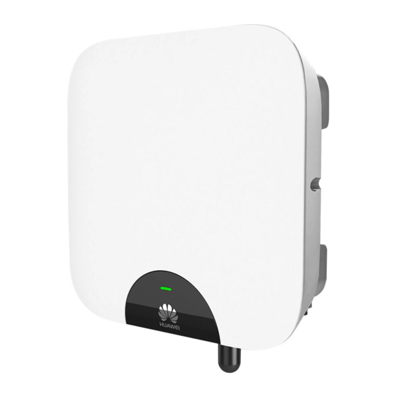
Summary of Contents for Huawei SUN2000-5KTL-L0
- Page 1 SUN2000-(2KTL-5KTL)-L0 Quick Guide Issue: 02 Part Number: 31509986 Date: 2019-04-27 HUAWEI TECHNOLOGIES CO., LTD.
-
Page 2: Packing List
4. Before installing the device, check that the package contents are intact and complete against the packing list. If any damage is found or any component is missing, contact your dealer. 5. Huawei shall not be liable for any device damage caused by the violation of instructions in this document. -
Page 3: Installing The Device
Overview (1) LED (2) Front panel (3) Mounting bracket (4) Mounting plate (5) Heat sink (6) Ventilation valve (7) DC switch (DC SWITCH) (8) DC input terminals (9) DC input terminals (PV1+/PV1–) (PV2+/PV2–) (12) AC output port (AC) (10) COM port (COM) (11) USB-4G port cover (USB-4G) (13) Antenna port (ANT) (14) Ground point... -
Page 4: Installing The Mounting Bracket
Dimensions If multiple inverters need to be installed, see SUN2000-(2KTL-5KTL)-L0 User Manual for the installation dimensions. Installing the Mounting Bracket Wall-mounted Installation Avoid drilling holes in the utility pipes and/or cables attached to the back of the wall. -
Page 5: Installing The Sun2000
Support-mounted Installation Prepare M8 stainless bolt assemblies (including flat washers, spring washers, and M8 bolts) with appropriate lengths as well as matched flat washers and nuts based on the support specifications. You are advised to apply anti-rust paint on the hole positions for protection. Installing the SUN2000 ... - Page 6 (Optional) Installing the Smart Dongle The USB-4G port is available only for a Smart Dongle, rather than a USB data cable. Install the SIM card in the direction shown by the silk screen and arrow on the slot. Press the SIM card until it snaps into place and locked, which means that the SIM card is ...
-
Page 7: Optional) Installing The Wifi Antenna
(Optional) Installing the WiFi Antenna The Smart Dongle and WiFi antenna cannot be used at the same time. Antenna port (ANT) Ensure that the WiFi antenna is installed securely. Connecting Cables Preparing Cables Prepare cables based on site requirements. Conductor Cross- Outer No. -
Page 8: Installing The Pe Cable
Installing the PE Cable Do not connect the neutral wire to the enclosure as a PE cable. Otherwise, electric shocks will be caused. Ground point NOTE Recommended: Apply silica gel or paint around a ground terminal after connecting the ground cable. - Page 9 Two-Core Cable (L and N) Click 2. Connect the AC connector to the AC output port, and then Check the route of the AC output power cable. AC output port (AC)
-
Page 10: Installing The Dc Input Power Cable
NOTE Plug insert To remove the AC connector, follow the steps of its installation in reverse order. Then remove the plug insert as shown in the right figure. Installing the DC Input Power Cable 1. Ensure that the PV string is well insulated to ground. 2. - Page 11 using metal stamping forming contacts Positive connector Positive metal terminal Negative Click connector Negative metal terminal Pull the DC input power Ensure that the cable will cable back to ensure that not be extracted after it is connected securely. crimped. Ensure that the cables are correctly connected.
- Page 12 (Optional) Installing the RS485 Communications Cable When laying out communications cables, separate them from power cables to avoid strong signal interference sources. Ensure that the exposed core wire is totally inserted into the cable hole and connected securely. ...
-
Page 13: Verifying The Installation
Click Verifying the Installation Acceptance Criteria The SUN2000 is installed correctly and securely. The WiFi antenna or Smart Dongle is installed correctly and securely. Cables are routed properly as required by the customer. Cable ties are secured evenly and no burr exists. The ground cable is connected correctly and securely. -
Page 14: Powering On The System
Powering On the System Before turning on the AC switch between the SUN2000 and the power grid, check whether the AC voltage is within the specified range. After turning on the AC switch, turn on the DC switch within 1 minute. Otherwise, the SUN2000 will start to export power to the power grid. - Page 15 5. (Optional) Observe the LED to check the operating status of the Smart Dongle. Description Color Status Yellow (blinking Steady on The Dongle is secured and powered green and red simultaneously) Green Blinking in a 2-second cycle (on Dialing (duration < 1 min) for 0.1s and then off for 1.9s) Blinking at long intervals (on for 1s The dial-up connection is set up...
- Page 16 2.(Optional)Installer Account Registration NOTE If you have an installer account, skip this step. Creating the first installer account will generate a domain named after the company. To create multiple installer accounts for the same company, log in to the FusionSolar and tap New User.
-
Page 17: Inverter Commissioning
3. Creating a PV Plant and an Account for User NOTE For details, see the FusionSolar App Quick Guide. You can scan the QR code to obtain it. Inverter commissioning 1. Access Inverter commissioning. Method 1: before login Method 2: after login... - Page 18 2. Connect to the inverter WiFi. Log in as installer, and perform Quick settings. • The initial password for connecting the inverter WiFi is Changeme • The initial password of the installer is 00000a • Use the initial password upon first power-on and change it immediately after login.
-
Page 19: Customer Service Contact
Customer Service Contact Region Country Phone Service Support Email France Germany Spain eu_inverter_support@huawei.com 0080033888888 Europe Italy Netherlands Other countries For details, see solar.huawei.com. Australia au_inverter_support@huawei.com 1800046639 Turkey tr_inverter_support@huawei.com 0080021686868 Malaysia Asia /1800220036 Pacific (+66) 26542662 (charged by apsupport@huawei.com local call) - Page 20 Huawei Technologies Co., Ltd. Huawei Industrial Base, Bantian, Longgang Shenzhen 518129 People's Republic of China solar.huawei.com...


