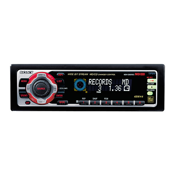
Sony MDX-C800REC Service Manual Supplement
Hide thumbs
Also See for MDX-C800REC:
- Operating instructions manual (262 pages) ,
- Service manual (74 pages) ,
- Installation/connections (2 pages)
Summary of Contents for Sony MDX-C800REC
- Page 1 MDX-C800REC US Model Canadian Model SERVICE MANUAL SUPPLEMENT-1 File this supplement with the service manual. Subject : Electrical Adjustments...
-
Page 2: Display Test
ELECTRICAL ADJUSTMENT TEST MODE ADJUSTMENT mode: SHUF indication off This set has the test mode functionality. The test mode should be Description of test always set before performing adjustments. Laser power adjustment mode Traverse adjustment mode <Setting the Test Mode> Focus bias adjustment mode 1. - Page 3 NOTES FOR ADJUSTMENT PREPARING A CONTINUOUSLY RECORDED DISC 1. Perform the following adjustments as listed when the optical pick- • This disc is used for focus bias adjustment and error rate check. up and IC400, IC402 and/or IC440 in the MD SERVO board This disc is prepared as follows: have been replaced: (1) Laser power adjustment...
-
Page 4: Laser Power Adjustment
For the measurement points, see page 7. <Setting the read power reference value> 8. Press 2 key. LASER POWER ADJUSTMENT LCD display Connection: laser power meter optical pick-up Mode No. 0.7 mW power objective lens (LD Power Adj.) digital voltmeter 9. -
Page 5: Traverse Adjustment
TRAVERSE ADJUSTMENT FOCUS BIAS ADJUSTMENT Connection: Procedure: 1. Set the test mode. (See page 2.) oscilloscope 2. Insert the continuously recorded disc (see page 3.) and press 5 key. MD servo board 3. Press 4 key and check the error rate in the current focus bias TP (TE) setting. -
Page 6: Mo Error Rate Check
11. Verify that the calculated point C error rate is “0.30” or less. MO ERROR RATE CHECK If more than “0.30”, adjust again from step 1. Procedure: 12. Press 4 key. The focus bias adjustment is completed. 1. Set the test mode. (See page 2.) 2. - Page 7 Measurement points: — MD SERVO BOARD (SIDE A) — I+3V...
- Page 8 MDX-C800REC Sony Corporation 9-870-144-82 2000F0411-1 Audio Entertainment Group Printed in Japan ©2000. 6 Published by ME General Engineering Dept.


