Sign In
Upload
Manuals
Brands
ABB Manuals
Multi-service Platforms
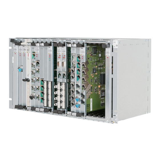
FOX615
ABB FOX615 Manuals
Manuals and User Guides for ABB FOX615. We have
1
ABB FOX615 manual available for free PDF download: Installation & User Manual
ABB FOX615 Installation & User Manual (98 pages)
Brand:
ABB
| Category:
Multi-service Platforms
| Size: 1.77 MB
Table of Contents
Table of Contents
3
1 Preface
11
Precautions and Safety
11
Symbols and Notations
11
Interfaces and Circuit Categories
12
Document History
12
Definition of Terms
12
Table 1: Electrical Interfaces and Circuit Categories
12
Table 2: Document History
12
2 Preparing for Installation
13
Installation General Instructions
13
Selection of the Installation Site
13
Options for Installation
14
Planning Guide Lines
15
Power Supply Principles
15
Power Supply Circuits
15
Wire Gauge
16
Figure 1: FOX615 Power Distribution
16
Circuit Breakers
17
Heat Evacuation and Installation
17
Units and Heat Dissipation
17
Subrack Installation
18
Arrangement in the Rack
19
Figure 2: Evacuation of Heated Air to the Rear (Recommended for 19- Inch Installation at the Bottom of a Cabinet)
19
Figure 3: Evacuation of Heated Air to the Front (Recommended for 19-Inch Installation at the Top of a Cabinet)
20
Figure 4: Arrangement of Stacked FOX with Heat Deflection Devices
21
Earthing Principles and Requirements
22
Earthing and Power Supply
22
Lightning and Over-Voltage Protection
23
Figure 5: Earthing and Power Supply Terminals of the FOX615 Subrack
23
EMC and ESD Considerations
24
Dimensions and Mechanical Installation Practice
26
19-Inch Installation Standard
26
Overview
26
Figure 6: 19-Inch Installation Standard for the FOX615
26
Subrack
27
Subrack with Front Cover
27
Figure 7: Mechanical Dimensions FOX615 Subrack
27
DUPF1 (Option)
28
Cable Tray
28
Figure 8: Mechanical Dimensions FOX615 Subrack with Front Cover and DUPF1
28
Figure 9: Mechanical Dimensions DUPF1 Dual Power Supply Connection Box (Option)
28
Famo1
29
Famo1-F
29
Figure 10: Mechanical Dimensions FOX615 Cable Tray
29
Figure 11: Mechanical Dimensions FAMO1 Fan Unit
29
Heat Deflection Shield 2 HU
30
Heat Deflection Shield 1 HU
30
Figure 12: Mechanical Dimensions FAMO1-F Fan Unit
30
Figure 13: Mechanical Dimensions Heat Deflection Shield 2 HU
30
ETSI Installation Standard
31
Overview
31
Figure 14: Mechanical Dimensions Heat Deflection Shield 1 HU
31
Figure 15: ETSI Installation Standard for the FOX615
32
ETSI Adapters
33
Table 3: Usage of ETSI Adapters
33
Table 4: Torques
36
Torques
36
3 Installation Procedures
37
Unpacking and Equipment Check
37
Before You Start
37
Packing of the Subrack and Accessories
38
Figure 19: Subrack Packing Assembly of the FOX615
39
FOX615 Equipment
40
Signal Cables
40
ETSI Adapters (Option)
41
Figure 20: FOX615 Installation with 11 HU ETSI Adapters
41
Table 5: ETSI Adapters
41
Captive Nuts
42
19-Inch Racks
42
Figure 21: FOX615 Fixing Positions in the 19-Inch Rack Relative to the Cable Tray
43
ETSI Racks
44
Cable Tray and Power Supply
44
Installing the Cable Tray
44
Figure 22: Cable Tray
44
Installing the DC Power Supply
45
Power Cable
45
Figure 23: FOX Power Supply Cable
45
Figure 24: Cable Tray and Installation of WAGO Connector Blocks and Power Cables
46
External Power Supply Circuit
47
Figure 25: Connecting Wires to the WAGO Connector Block
47
Signal Cables
49
Tying Signal Cables to the Cable Tray
49
Figure 26: Cable with Ferrite Toroid Sample
49
Figure 27: Cable with EMC Filter Sample
49
Figure 28: Installation and Position of Connectors and Cables with EMC Filter with Respect to the Front Line of the Cable Tray
50
Units
51
Fan Unit
51
Tying Cables to Their Connection Points
51
Subrack
53
Installing DUPF1 (Option)
53
Figure 29: DUPF1 Installation
55
Installing the FAMO1 or FAMO1-F Power and Alarm Cable (Optional)
57
Figure 30: FOX Subrack with DUPF1 Installed
57
Figure 31: FOX Subrack FAMO1 or FAMO1-F Power and Alarm Cable Installation
58
Installing the Subrack
59
Prerequisites
59
Subrack Installation
59
Subrack Earthing
60
Figure 32: Earthing / Bonding Points of the FOX Subrack
61
Subrack Power Supply
62
Local Power Interfaces
62
Single Circuit Power Supply
62
Figure 33: Principles of Single Circuit Power Supply
63
Dual Power Supply (DUPF1 Option)
64
Figure 34: Principles of Two Circuits Power Supply
64
Fan Unit or Alarm Unit (Option)
66
Installing FAMO1 or FAMO1-F
66
FOX Interface
66
Figure 35: FAMO1 or FAMO1-F Power and Alarm Cable
66
Figure 36: Installation of the FAMO1 or FAMO1-F Power and Alarm Cable
67
Alarm Interfaces
68
Interfaces and Connectors
68
Figure 37: FAMO1 and FAMO1-F Alarm Interfaces
68
Figure 38: Molex Connector Frames and Crimp Terminals
68
Alarm Signal Input Interfaces
69
Figure 39: FAMO1 and FAMO1-F Alarm Signals Input Interfaces
69
Figure 40: Molex Connector Frame Alarm Signal Inputs
69
Table 6: Alarm Input Interfaces Pin Connection
69
DUPF1 Alarm Interface
70
Figure 41: DUPF1 Alarm Interface Connection
70
Table 7: DUPF1 Alarm Input Interfaces Pin Connection
70
Alarm Signal Output Interface
71
Figure 42: FAMO1 and FAMO1-F Alarm Signals Output Interface
71
Figure 43: Molex Connector Frame System Alarm Signal Outputs
71
Table 8: Alarm Output Interface Pin Connection
71
Heat Deflection Shield
72
Orientation of the Shield
72
Figure 44: Alarm Output Contact Scheme (no Alarms, Inactive State)
72
Figure 45: Alignment of the Heat Deflection Shield for Evacuation of Heated Air to the Rear
73
Installing the Shield
74
Figure 46: Alignment of the Heat Deflection Shield for Evacuation of Heated Air to the Front
74
Final Steps
75
Tightening of Screws
75
Cable Clamps, Earthing Bar and EMC Clips
75
Figure 47: Cable Clamps and Earthing Bars (Conductive Foam in Bars and Clamps Is Dark Shaded)
75
Figure 48: Detail of Unlocking a Cable Clamp with a Screwdriver (Application with Left Clamp Shown)
76
Figure 49: Mounting of Three Plus Three EMC Clips to the Earthing Bars
77
Units and Signal Cables
78
Inserting Units in the Subrack
78
Figure 50: Insertion of Units in the Subrack
79
Connecting Signal Cables
80
Clamping Cables to the Subrack Earthing Bar
81
Removing Units
81
Figure 51: Removal of Units from the Subrack
81
Front Cover
83
Mounting the Front Cover
83
Figure 52: Installing the Front Cover to the Subrack
83
Removing the Front Cover
85
Figure 53: Removing the Front Cover from the Subrack
85
4 Checklists
87
Overview
87
NE and Units
87
Table 9: Checklist FOX Equipment
87
Options
88
Cables
88
Cables for Alarm Interfaces
88
Table 10: Checklist FOX Equipment
88
Table 11: Checklist ETSI Adapter Options
88
Computer Cables and Adapters
89
Signal Cables
89
Table 12: Checklist Alarm Interface Connector Set
89
Table 13: Checklist Computer Cables
89
Installation Material
90
Table 14: Checklist for Material
90
Tools
91
Test Equipment
91
Table 15: Checklist for Tools (Installation)
91
5 Annex
93
Associated FOX Documents
93
Associated Documents of Standard Bodies
94
Declaration of Conformity
94
Table 16: Associated Documents of Standard Bodies
94
Feature Licences
95
Advertisement
Advertisement
Related Products
ABB FOX61 Series
ABB FOCH
ABB FEX500
ABB i-bus KNX FCL/S 2.6.1.1
ABB FSM4000-S4
ABB SwirlMaster FSS450
ABB FS4000-ST4
ABB FCB400 Series
ABB ReliaMod RMM FE6RCLL
ABB F-ARI2Test A-63/0.03
ABB Categories
Industrial Equipment
Controller
Measuring Instruments
Battery Charger
DC Drives
More ABB Manuals
Login
Sign In
OR
Sign in with Facebook
Sign in with Google
Upload manual
Upload from disk
Upload from URL