Sign In
Upload
Manuals
Brands
Siemens Manuals
Inverter
MICROMASTER 411
User Manuals: Siemens MICROMASTER 411 Inverter
Manuals and User Guides for Siemens MICROMASTER 411 Inverter. We have
6
Siemens MICROMASTER 411 Inverter manuals available for free PDF download: Operating Instructions Manual, Getting Started Manual
Siemens MICROMASTER 411 Operating Instructions Manual (164 pages)
Siemens Welding System - AC/DC Welding Inverter User Manual
Brand:
Siemens
| Category:
Inverter
| Size: 4.63 MB
Table of Contents
Safety Instructions
7
Table of Contents
11
1 Overview
15
Micromaster 411 / Combimaster 411
16
Design Features
17
Main Characteristics
17
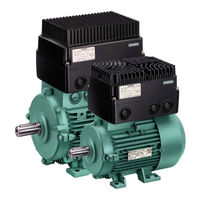
Figure 1-1 MICROMASTER 411 and COMBIMASTER 411 Variable Frequency Inverters
18
Performance Characteristics
18
2 Installation
19
Installation after a Period of Storage
21
Figure 2-1 Forming
21
Ambient Operating Conditions
22
Humidity Range
22
Electromagnetic Radiation
22
Mechanical Installation MICROMASTER 411
23
Installation Procedure
24
Figure 2-2 MICROMASTER 411, Internal Layout
25
Figure 2-3 MICROMASTER 411 Case Size B Dimensions
26
Figure 2-4 MICROMASTER 411 Case Size C Dimensions
26
Table 2-1 MICROMASTER 411 Dimension Detail
26
Figure 2-5 Cable Glands
27
Figure 2-6 Installation of Cable Gland
27
Installation of Cable Glands
27
Table 2-2 Gland Plate Detail
28
Figure 2-7 MICROMASTER 411 Gland Dimensions
28
Mechanical Installation COMBIMASTER 411
30
Figure 2-8 COMBIMASTER 411 Case Size B Dimensional Detail
31
Figure 2-9 COMBIMASTER 411 Case Size B Dimensional Detail
32
Electrical Installation
33
Operation with Residual Current Device
33
Operation with Long Cables
33
Line and Motor Connections
34
50 L
34
Motor Connections for Star/Delta
35
Power Connections
35
Figure 2-10 Motor and Power Supply Connections
36
Figure 2-11 Control Terminals
37
Figure 2-12 PTC Connections
38
Motor Ptc Connections
38
3 Commissioning
41
Block Diagram
43
Figure 3-1 COMBIMASTER 411 & MICROMASTER 411 Block Diagram
43
General Information
44
Commissioning Procedure Overview
45
Figure 3-2 MICROMASTER 411 / COMBIMASTER 411 Commissioning Guide
45
Figure 3-3 Ramp Time Jumpers
46
Table 3-1 Ramp Time Adjustment Jumpers
46
Table 3-2 Ramp Time Jumper Behaviour
47
Figure 3-4 Control Circuit Jumpers
48
Table 3-3 Control Circuit Jumper Settings
48
Table 3-4 Control Circuit Jumper Behaviour
48
Table 3-5 Default Settings for BOP Operation
50
Figure 3-5 Basic Operator Panel Controls
51
Figure 3-6 Changing Parameters Via the BOP
52
Figure 3-7 Typical Motor Rating Plate Example
55
Motor Data for Parameterization
55
Reset to Factory Default
55
General Operation
56
Figure 3-8 Default Setup Terminal Connections
56
Figure 3-9 Connect BOP/AOP with the MICROMASTER 411
58
4 Using the MICROMASTER 411 / COMBIMASTER 411
61
Frequency Setpoint
62
Command Sources (P0700)
63
OFF and Braking Functions
63
Control Modes (P1300)
65
Faults and Warnings
65
5 System Parameters
67
Introduction to System Parameters
68
Parameter Structure
69
Figure 5-1 Parameter Structure with Filter (P0004)
69
Parameter List (Short Form)
70
6 Troubleshooting
79
Troubleshooting with the Inverter LED
80
Troubleshooting with the Basic Operator Panel
80
Table 6-1 Inverter LED Indication
80
Faults and Alarms
81
Alarm Messages
87
7 Specifications
93
Technische Daten
94
Table 7-1 MICROMASTER 411 / COMBIMASTER 411, Leistungsdaten
94
Case Size Rating Information
95
Table 7-2 Case Size B
95
Table 7-3 Case Size C
95
Tightening Torque, Cable Cross Sections for Power Supply and Motor Terminals
96
Tightening Torque for Fixing Screws
96
Table 7-4 Power Supply & Motor Terminal Wire Sizes/Tightening Torques
96
Table 7-5 Fixing Screw Recommended Tightening Torque
96
Fuses and Circuit Breakers
97
Table 7-6 MICROMASTER 411/COMBIMASTER 411 Fuses and Circuit Breakers
97
8 Options
99
MICROMASTER 411/COMBIMASTER 411 User Options
99
MICROMASTER 411/COMBIMASTER 411 Programming Options
100
Table 8-1 Key to Programming Options
100
Basic Operator Panel (BOP) / Advanced Operator Panel (AOP)
101
PROFIBUS Module
102
EM Brake Module
103
MICROMASTER 411 Operator Panel Mounting Kit
104
PC to Inverter Connection Kit
105
PC to AOP Connection Kit
106
Door Mounting Kit for Single Inverter Control
107
Wall Mounting Kit for MICROMASTER 411
108
9 Electro-Magnetic Compatibility (EMC)
109
Electro-Magnetic Compatibility (EMC)
110
Table 9-1 Environment - General Industrial
111
Table 9-2 Environment - Filtered Industrial
111
Table 9-3 Environment - Filtered for Residential, Commercial and Light Industry
112
Emc Compliance Tests
113
Table 9-4 EMC Compliance Table
113
Table 9-5 MICROMASTER 411 Measured Results
113
10 Engineering Information
115
Current Limit and Overload Operation
116
Figure 10-1 Current Limit Interaction
117
Table 10-1 Measured Current Monitoring Accuracy
117
Figure 10-2 PTC Resistor Connections
118
Internal Overtemperature
119
Table 10-2 Trip Levels
119
Control and Operating Modes
120
Figure 10-3 Boost-Level
120
Figure 10-4 Quick Response with Overshoot: P2280 = 0.30; P2285 = 0.03 S
124
Figure 10-5 Quick Response with Overshoot, but Instability:p2280 = 0.55; P2285 = 0.03 S
124
Figure 10-6 Damped Response: P2280 = 0.20; P2285 = 0.15 S
125
Figure 10-7 Response to 5 Hz Step: L = 100 Ms
126
Figure 10-8 Response to 5 Hz Step: T = 700 Ms
127
Figure 10-9 Step Response in PI Control with P2280 = 9.84 and P2285 = 0.30
127
Figure 10-10 PI Basic Block Diagram
128
Pi Output Limits
128
Figure 10-11 Energy Saving Mode 1
130
Figure 10-12 Energy Saving Mode 2
131
Braking
132
Figure 10-13 Frequency Ramp down
132
Figure 10-14 DC Braking
133
Figure 10-15 Compound Braking
134
Derating Factors
135
Figure 10-16 Reduktionsfaktoren durch die Umgebungstemperatur
135
Figure 10-17 Derating with Altitude
135
Table 10-3 Derating with Switching Frequencies
136
Thermal Protection and Automatic De-Rating
137
Operation from Unearthed Supplies
137
Lifetime of Inverters
137
Working with Binary Connectors (Bico)
138
Table 10-4 Bico Connections (R0019 to R0054)
141
Table 10-5 Bico Connections (R0055 to R1119)
142
Table 10-6 Bico Connections (R1170 to R2050)
143
Table 10-7 Bico Connections (R2053 to R2294)
144
Harmonic Currents
145
Table 10-8 Three Phase 400 V Connection
145
Use of MM4 Input Chokes
146
Power Losses
146
Figure 10-18 Power Losses MICROMASTER 411 / COMBIMASTER 411
146
Shock and Vibration
147
Profibus
148
PROFIBUS Module
149
Table 10-9 Maximum Cable Lengths for Data Transfer Rates
150
Table 10-10 Technical Data - 411 PROFIBUS Module
151
Table 10-11 PROFIBUS Ordering Information
151
Variant Independent Options
152
Appendices
155
A Applicable Standards
155
List of Abbreviations
156
MICROMASTER 411 / COMBIMASTER 411 Parts Identification
157
Index
158
Advertisement
Siemens MICROMASTER 411 Operating Instructions Manual (74 pages)
PROFIBUS Module
Brand:
Siemens
| Category:
DC Drives
| Size: 2.68 MB
Table of Contents
Definitions, Warnings
6
Table of Contents
8
1 Description of the MICROMASTER PROFIBUS Option Module
11
Figure 1-1 PROFIBUS Communication Module
11
Technical Data
12
Functionality
12
2 General Definition of PROFIBUS-DP
13
Definition
13
RS-485 Transmission System
13
General Information about RS-485 Transmission Installation
13
Bus Accessing Mode
14
Data Exchange Via PROFIBUS-DP
14
Standards, Guidelines and Other Information
15
3 Communication with MICROMASTER 4 Via PROFIBUS-DP
17
Cyclical Data of MICROMASTER 4 Via PROFIBUS-DP
17
Useful Data Structure as Defined in Profidrive Profile 2.0 and 3.0
17
MICROMASTER 4 Reaction Time
21
Acyclic Data Transmission
21
Control and Status Words
22
PKW Mechanism for Processing Parameters
24
Table 3-3 Request Identifier (Master -> Inverter)
25
Table 3-4 Response Identifier (Inverter -> Master)
25
Table 3-5 Fault Numbers for "Cannot Process Request" Response
26
4 Connection to PROFIBUS-DP
31
Installing the PROFIBUS-Option Module
31
List of Accessories
31
Preparation of Inverter Terminal Housing
31
Table 4-1 List of Accessories
31
Figure 4-1 Removing Inverter Cover
32
Figure 4-2 Removing the Filter and I/O Boards
32
Figure 4-3 Gland Plate or "Knockout" Removal
33
Figure 4-4 Fitting Gland Fixing Plates
33
PROFIBUS Option Module Installation
34
Figure 4-5 PROFIBUS Module Layout
34
Figure 4-6 PROFIBUS Module Fixing to Inverter
34
Figure 4-7 Fitting the Communications Cable
35
Connection of an External 24 V Voltage Supply
36
Table 4-2 Torque Values
36
Connecting the Bus Cable Using RS485 Bus Connectors
37
Maximum Cable Lengths
37
Comms Link Connector
38
Connecting the Bus Cable
38
Figure 4-8 PROFIBUS Cable Strip Lengths
38
Bus Terminator
39
Screening the Bus Cable / EMC Precautions
39
Figure 4-9 Switch Positions for Bus Terminating Resistors
39
Figure 4-10 Bus Terminating Network
39
5 Configuration of the PROFIBUS
42
PROFIBUS Address
42
Figure 5-1 Jumpers and Termination Switch
42
Table 5-1 PROFIBUS Jumper Settings
42
PROFIBUS Parameters
43
Table
43
Table 5-5 Communication Board Functions
45
6 Configuration for S7 PLC
49
Configuration Using SIMATIC Manager
49
Figure 6-1 New Project Screen
49
Figure 6-2 Select Station Screen
49
Figure 6-3 Hardware Configuration Window
50
Figure 6-4 Hardware Selection (SIMATIC 300)
50
Figure 6-5 Select Type of Racking
51
Figure 6-6 Select Type of Power Supply
51
Figure 6-7 Select Type of CPU
52
Figure 6-8 Select PROFIBUS Address Screen
52
Figure 6-9 Selection of Baud Rate
52
Figure 6-13 Dragging and Dropping the MICROMASTER 4 Profile
54
Figure 6-14 Selecting the PROFIBUS Address
54
Figure 6-15 Drag and Drop PKW and PZD into Hardware Table
55
Figure 6-16 Select I/O Module
55
Setting Parameters
56
Confirmation of PROFIBUS Communications
56
Controlling the Inverter with a PLC
56
7 Links to PROFIBUS-DP Master Systems
59
General
59
Operation on SIMATIC S7
59
Exchanging Data Using Internode Communication Function
61
SIMATIC HMI (Human-Machine Interface)
63
Figure 7-2 Example of Application of Internode Communication
63
Operation on External Master Systems
65
8 Diagnostics and Troubleshooting
67
Diagnostics Using Alarm Number (Alarms and Faults)
67
Alarms
67
Table 8-1 Alarm Displays on Inverter
67
Faults
68
Diagnostics Using Diagnostic Parameter
68
Standard Diagnostics
68
Table 8-2 Fault Displays on Inverter
68
Table 8-3 Standard Diagnostic Parameter
68
Table 8-4 Parameter Accessing Errors
69
Special Diagnostics for Start-Up Personnel
70
Table 8-5 Special Diagnostics
70
9 Appendix
71
Technical Data
71
EMC Information
71
10 Glossary
72
Siemens MICROMASTER 411 Operating Instructions Manual (22 pages)
Electromechanical Brake Control Option
Brand:
Siemens
| Category:
Inverter
| Size: 2.71 MB
Table of Contents
Table of Contents
7
1 Description MICROMASTER 411 & COMBIMASTER 411 EM Brake Option
9
Introduction
9
Figure 1-1 EM Brake Module Layout
10
2 Installation Instructions
11
Installing the EM Brake Option Module
11
List of Accessories
11
Preparation of Inverter Terminal Housing
11
Figure 2-1 Removing Inverter Cover
12
Figure 2-2 Removing the Filter and I/O Boards
12
Figure 2-3 Gland Plate or "Knockout" Removal
13
Figure 2-4 Fitting Gland Fixing Plates
13
EM Brake Option Module Installation
14
Figure 2-5 EM Brake Module Layout
14
Figure 2-6 EM Brake Module Fixing to Inverter
15
Figure 2-7 Fitting the Control Cable
15
Torque Values
16
Power Supply Cable Requirements
16
3 Engineering Information
18
Parameters for the EM Brake Control Option
18
Table 3-1 Jumper Settings
18
Figure 3-1 P1215 Braking Profile
19
Relationship between Supply and Coil Voltage
21
Advertisement
Siemens MICROMASTER 411 Operating Instructions Manual (28 pages)
AS-i Module
Brand:
Siemens
| Category:
Control Unit
| Size: 0.81 MB
Table of Contents
Table of Contents
8
1 Description
9
2 Installing the AS-I Module
11
Preparation of Inverter Terminal Housing
12
AS-I Module Installation
13
Addressing the AS-I Module
15
3 Commissioning
17
Parameter Settings
17
AS-I Module Parameters
18
AS-I Use Data
19
4 Diagnostics and Troubleshooting
21
5 Technical Data
23
Technical Specifications
23
EMC Information
23
Siemens MICROMASTER 411 Getting Started Manual (20 pages)
Brand:
Siemens
| Category:
Inverter
| Size: 2.02 MB
Table of Contents
Table of Contents
1
Combimaster
2
Installation to Motor
3
Installation
3
Electrical Installation
7
Avoiding Electro-Magnetic Interference
9
Commissioning COMBIMASTER 411/ MICROMASTER 411
9
General Information
9
Commissioning Procedure Overview
10
Quick Commissioning
15
Commissioning with BOP
15
Reset to Factory Defaults
16
Additional Control Applications
16
Further Information
16
Dimensions
16
MICROMASTER 411 - Dimensions
16
COMBIMASTER 411 - Dimensions
17
Micromaster 411 & Combimaster
18
Siemens MICROMASTER 411 Getting Started Manual (20 pages)
Brand:
Siemens
| Category:
Inverter
| Size: 9.35 MB
Table of Contents
Table of Contents
1
1 Installation
3
Installation to Motor
3
Electrical Installation
6
2 Avoiding Electro-Magnetic Interference
8
3 Commissioning COMBIMASTER 411/MICROMASTER 411
8
General Information
8
Commissioning Procedure Overview
9
4 Quick Commissioning
14
Commissioning with BOP
14
Reset to Factory Defaults
15
Additional Control Applications
15
Further Information
15
5 Dimensions
15
MICROMASTER 411 - Dimensions
15
COMBIMASTER 411 - Dimensions
16
Advertisement
Related Products
Siemens MICROMASTER 430
Siemens MICROMASTER 420
Siemens MICROMASTER 440 Series
Siemens Micromaster Eco
Siemens micromaster 410
Siemens MICROMASTER Vector Series
Siemens MICROMASTER Vector MMV25
Siemens MICROMASTER Vector MMV12
Siemens MICROMASTER Vector MMV55
Siemens MICROMASTER Vector MMV75
Siemens Categories
Industrial Equipment
Controller
Control Unit
Oven
Washer
More Siemens Manuals
Login
Sign In
OR
Sign in with Facebook
Sign in with Google
Upload manual
Upload from disk
Upload from URL