Sign In
Upload
Manuals
Brands
Sony Manuals
DVR
DNW-A45P
Sony DNW-A45P Manuals
Manuals and User Guides for Sony DNW-A45P. We have
4
Sony DNW-A45P manuals available for free PDF download: Maintenance Manual, Operation Manual
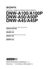
Sony DNW-A45P Maintenance Manual (506 pages)
Digital Video Hybrid Recorder
Brand:
Sony
| Category:
Measuring Instruments
| Size: 10 MB
Table of Contents
Table of Contents
3
Purpose of this Manual
10
Contents
10
Manual Structure
10
Related Manuals
12
Caution for Handing the Unit with Built-In Hdds (for Part 2)
13
Service Overview
15
Circuit Protection Device (Fuse and IC Link)
15
Memory IC with Backup Battery
16
Nv-Ram
16
Alignment Tape
18
Extension Board
21
PLCC IC Removal
21
Service Action after Replacing or Repairing the Mounted Circuit Board
22
Board
22
Board (BKNW-105)
24
Board (BKNW-103)
24
Board
24
Board (BKDW-505/506)
25
Board
25
Board (BKNW-105)
25
Board
26
Board
27
Board
28
Board
29
Perfection after Replacing the Hard Disk Drive
30
Electrical Alignment Overview
31
Notes on Electrical Alignment
31
Outline of Electrical Alignment
31
Required Equipment/Tools
32
Internal Video Test Signal
33
Electrical Alignment
37
Power Supply Line Alignment
38
Output Voltage Check
38
Output Voltage Adjustment
39
Dial Pulse Adjustment (PTC-69 Board)
40
Demagnetization Head Driving Voltage Adjustment (MS-50 Board)
42
Servo System Alignment
43
Adjustment Overview
43
Servo Adjustment Data Initialization
44
Servo Continuity Automatic Adjustment
44
Capstan Free Speed Adjustment
44
RF Switching Position Adjustment
45
RF System Alignment (EQ-56 Board)
46
Adjustment Overview
46
Betacam SX Format Overall RF System Adjustment
47
(EQ RF Output Level) Adjustment
48
Betacam / Betacam SP Format PB System
48
Recording Current Adjustment
51
-6. Audio System Adjustment
52
Adjustment Overview
52
Are Not Needed
52
Audio System Adjustment (APR-12/13 Boards)
52
Common Preparation
54
Analog Audio Outputs (CH1/2/3/4) Adjustment (APR-13 Board)
56
Analog Audio Offsets (CH3/4) Adjustment (APR-13 Board)
57
Analog Audio Inputs (CH3/4) Adjustment (APR-13 Board)
58
Input Level Adj
58
Analog Audio Monitor Outputs (L/R) Adjustment (APR-12 Board)
59
It to VIDEO OUTPUT COMPOSITE 3 (SUPER)
59
This Monitor Is for Menu Displaying. be Sure to Connect
59
Analog Audio Offsets (CH1/2) Adjustment (APR-12 Board)
60
Analog Audio Inputs (CH1/2) Adjustment (APR-12 Board)
61
LAU PB System Adjustment (APR-12 Board)
63
Adjustment Overview
68
Video System Alignment (VPR-17 Board)
68
Preparation in Standard System
70
Composite Video Output Adjustment (Standard System)
71
Component Video Output Adjustment (Standard System)
73
Component Video Output (Betacam) Adjustment (525/60 System)
75
(Standard System Only)
77
Reference Color Frame Pulse Check
77
Internal 4Fsc Frequency Adjustment
79
Preparation in Another System
80
Composite Video Output Adjustment (Another System)
81
Component Video Output Adjustment (Another System)
83
Component Video Output (Betacam) Adjustment (for DNW-A100P/A50P/A45P Only in 525/60 System)
84
Adjustment Overview
85
Analog Betacam PB System Alignment
85
Common Preparation
90
Initial Data Settings
91
Cosine Equalizer Adjustment
92
EQ RF Output Level Adjustment
92
Cosine Equalizer Provisional Adjustment
100
DM RF Output Level Adjustment
102
OMC Carrier Balance Adjustment
104
OMC Carrier Balance Provisional Adjustment
107
Demodulator Limiter Balance Adjustment
108
-8-11. Non-Liner Output Level Adjustment
110
Non-Liner Output Level Adjustment
110
Non-Liner Output Level Adjustment
111
Alignment Tapes
112
Before Removing DM-89 Board, Wait for more than 30
112
Check the Setting on the Upper Control Panel
112
Extend the DM-89 Board with an Extension Board EX-377. N
112
Extension Board: EX-377 (Part No. J-6269-810-A)
112
For NTSC: CR5-1B
112
PB Frequency Response Adjustment
112
Preparing Tools
112
Remote/Local
112
Seconds after Turning off the POWER Switch
112
Before Starting the Adjustment, Warm up the VTR and
113
Check that the Equipment Has Warmed up
113
During Play Back the Alignment Tape in PLAY Mode
114
METAL y Adjustment
114
Drop-Out Compensation Equalizer Adjustment
118
NTSC Model
118
PAL Model
118
Cr5-1B (Ntsc) / Cr5-1B Ps (Pal)
119
DM RF Output Level Readjustment
119
Board (Side A)
120
RF Envelope Adjustment
120
Search Picture Adjustment
122
Guard Band Width Adjustment
124
Component Output Level Adjustment
126
A/D Clamp DC Level Adjustment
129
VCO Lock-In Range Adjustment
130
TBC VCO Free-Running Adjustment
131
FAST VCO Tracking Adjustment
132
PB Video Phase Adjustment
133
TBC Y/C Delay Rough Adjustment
136
Impact Error Offset Adjustment
138
TBC Y/C Delay Adjustment
139
VISC Phase Adjustment
141
TBC Remote Control Offset Adjustment (FP-91 Board)
145
Adjustment Overview
147
SDI/SDTI I/O Lines Adjustment (CP-297 Board)
147
VCO Free-Running Frequency Automatic Adjustment
148
VCO Free-Running Frequency Manually Adjustment
149
Adjustment Overview
150
LTC Alignment and Full Erasure Current Check (TC-96 Board)
150
LTC Playback Level Check
151
LTC Recording Level Check
152
Full Erasure Current Check
153
LTC Erasure Current Check
153
Electrical Alignment for Optional Boards
155
Adjustment
156
Board (BKDW-505/506)
156
Adjustment
166
Board (BKNW-103)
166
Operation Check
168
Adjustment
169
Board (BKNW-104)
169
Board and DIF-44 Board (BKNW-105)
182
Operation Check
182
Index
185
Threading End Mode and Unthreading End Mode
188
L Cassette Position and S Cassette Position
190
Basic Knowledge
192
Upper Drum Assembly Replacement
193
Drum Assembly Replacement
202
Cleaning Roller and Video Head Cleaner Assembly Replacement
211
AT Head Cleaner Replacement
216
Air Filter Replacement
219
Pinch Roller Replacement
221
CTL Head Replacement
224
Reel Motor Assembly Replacement
228
Replacement Procedure of the Reel Motor Assembly
228
Reel Motor Shaft Slantness Adjustment
236
Cassette Pillar Height Adjustment
239
Reel Table Height Adjustment
241
Reel Brake Clearance Check
244
Reel Brake Release Amount Adjustment
245
Reel Table Rotation Sensor Position Adjustment
247
Capstan Motor Replacement
250
AT Head Replacement
255
Pinch Solenoid Replacement
260
Replacement Procedure of the Pinch Solenoid
260
Pinch Press Clearance Adjustment
268
Fan Motor Replacement
270
Fan Motor (Rear) Replacement
271
Fan Motor (PS) Replacement
274
Fan Motor (HDD) and Fan Motor (MD) Replacement
275
Brush Slip Ring Assembly Replacement
281
Brake Solenoid Replacement
284
S Tention Regulator Assembry Replacement
294
T Tention Arm Replacement
296
T Drawer Arm Replacement
300
Slant Guide Slantness Adjustment
305
Gear Box Assembly and Threading Motor Replacement
310
Threading Ring and Ring Roller Replacement
317
Reel Table Assembly Replacement
333
Brake Lining Replacement
336
Tape Guide Replacement
340
Tape Cleaner Replacement
342
Full-Erase Head Replacement
344
Cleaning Solenoid Replacement
349
Reel Shift Gear Replacement
355
Reel Shift Motor Replacement
360
Cassette Compartment Motor Replacement
365
Power Supply Block Replacement
369
Caution for Handling the Hard Disk Drive
373
Hard Disk Drive Replacement
373
Removal/Installation of Hard Disk Drive Unit
373
Hard Disk Drive Replacement
377
Board
382
Board
385
Board
386
Board (BKNW-103)
386
Board
387
Board
390
Board
392
Board
393
Board
397
Board
399
Board
400
Board
401
Board
404
Board
406
Electrical Alignment after Replacement of Main Parts
413
General Information for Electrical Alignment
413
Notes on Electrical Alignment
413
Equipment and Tools Required
414
Content of Alignment Tapes
416
Servo/Eq Alignment after Replacing the Drum
419
Drum Phase Adjustment
420
PB Equalizer Adjustment
421
Recording Current Adjustment
422
Analog Video Playback System Adjustment after Replacing the Drum
423
Preparation
425
EQ RF Output Level Adjustment
428
DM RF Output Level Pre-Adjustment
431
OMC Carrier Balance Adjustment
433
Demodulator Limiter Balance Adjustment
436
OMC Carrier Balance Adjustment (Provisional)
436
PB Frequency Response Adjustment
439
DM RF Output Level Adjustment
443
RF Envelope Adjustment
445
Impact Error Offset Adjustment
446
TBC Y/C Delay Adjustment
447
Electrical Adjustment after Replacing the at Head
449
Preparation
450
LAU PB Frequency Response Adjustment
452
LAU Dolby Level Adjustment
454
LAU PB Level Adjustment
455
LAU PB Phase Adjustment
456
LTC Erasure Current Adjustment
457
LTC PB Level Check
457
LTC OA Check
458
LTC Erase Ratio Check
459
Tape Path Alignment
461
Tape Path Adjustment
462
AT Head Zenith Check and Adjustment
466
Tape-Running Check and Adjustment
468
Video Tracking Check and Adjustment
474
CTL Head Height Check and Adjustment
486
CTL Head Position Check and Adjustment
488
AT Head Height Check and Adjustment
491
AT Head Azimuth Check and Adjustment
494
AT Head Head-To-Tape Contact Check and Adjustment
497
AT Head Position Check and Adjustment
500
Audio Level Check and Adjustment in REV Mode
502
Advertisement
Sony DNW-A45P Maintenance Manual (416 pages)
Digital video hybrid recorder
Brand:
Sony
| Category:
DVR
| Size: 5.95 MB
Table of Contents
Table of Contents
5
Manual Structure
10
Purpose of this Manual
10
Contents
10
Related Manuals
11
Caution for Handling the Unit with Built-In HDD (for Part 1)
12
Installation
13
Installation Procedure
13
Supplied Accessories
13
Operating Conditions
14
Power Supply
14
Voltage and Power Requirements
14
Power Cord
14
Installation Space
15
Rack Mounting
16
Matching Connectors and Cables
21
Signal Inputs and Outputs
22
Switch Settings on Connector Panel
25
Switch and Shorting Plug Setting on PC Boards
26
Board
26
Board
32
SSX Board
34
Mode Switching of Search Dial
35
Setup Menu (ITEM F-Series)
36
Menu Operation
36
F-Series Items
37
Reference System
38
Switching between 525/625 Line Systems
39
Settings and Adjustment When Peripheral Equipment Is Connected
40
Time Code Setting
40
System Phase Alignment
41
Setup Menu Setting
41
Setting When BKNW-116 Is Connected
42
Installation of BKDW-505/506
43
Procedure
43
Check after Installing
44
Installation of BKNW-103
49
Procedure
49
Check after Installing
51
Installation of BKNW-104
52
Procedure
52
Adjustment after Installing
53
Installation of BKNW-105
67
Procedure
67
Check after Installing
70
Service Overview
73
Notes on Power Supply Block
73
Note on Resetting the Circuit Breaker
73
Cleaning When the Heads Are Clogged
73
Removal/Installation of Cabinet
74
Control Panels Removal/Installation
75
Plate MD Assembly Removal/Installation
77
Cassette Compartment Removal/Installation
78
Lower Control Panel Assembly Removal/Installation
79
Circuit Function
80
Location of Main Part
82
Printed Circuit Boards, Power Supply Unit
82
And HDD Units Location
82
Main Mechanical Parts Location
85
Function and Location of Sensors
86
System of Cassette
88
Function of Leds on Circuit Boards
90
How to Take out the Cassette When the Tape Is Slacking
94
Pulling Out/Insertion of Plug-In Board
95
Fixtures and Adjustment Equipment List
96
Fixtures
96
Equipment for Adjustment
98
Isr
99
Overview
99
Information of Connecting Cable
100
Procedure for Hard Disk Drive Check
102
Error Message
103
Overview of Error Message
103
Details of Error Messages
105
Maintenance Mode
135
Overview of Maintenance Mode
135
TAPE Maintenance Mode (M0)
140
Overviews
140
SERVO CHECK Mode (C0)
148
RF CHECK Mode (C1)
165
AUDIO/VIDEO CHECK Mode (C2)
169
BETACAM PB CHECK Mode (C3)
172
OTHERS CHECK Mode (C4)
173
SERVO ADJUST Mode (A0)
178
RF ADJUST Mode (A1)
185
AUDIO/VIDEO ADJUST Mode (A2)
193
BETACAM PB ADJUST Mode (A3)
202
DISK Maintenance Mode (M1)
205
Outline
205
Error Counter Display Menu (D0)
206
Device Information Display Menu (D1)
207
HDD Diagnosis Menu (D2)
208
HDD Installation Menu (D3)
210
BLACK File Installation Menu (D4)
211
Zone Configuration Menu (D5)
213
Disk Cleaning Menu (D9)
216
Error Logger Display Mode (M2)
218
Outline
218
Display Mode
219
Setting Mode
221
Periodic Maintenance and Inspection
223
Periodic Maintenance
223
Index
223
Periodic Replacement and Check Item Table
224
Hours Meter
226
Cleaning
227
Cleaning Using Cleaning Tape
227
General Information for Cleaning Using Cleaning Cloth
227
Tape Running Surface of Upper Drum and Video Heads Cleaning
229
Tape Running Surface of Lower Drum and Lead Surface Cleaning
230
Stationary Heads Cleaning
231
Tape Running System and Tape Cleaner Cleaning
232
Fan Motors Cleaning
233
Cassette Compartment and Cassette Supports Cleaning
234
Video Head Tip Protrusion Check
235
Head Tip Protursion Measurement
235
Brush Slip Ring Assembly Removal/Reinstallation
238
Replacement of Plug-In Boards
239
Service Overview for Plug-In Board Replacement
239
Notes on Plug-In Board Replacement
239
Service Action Before/After Plug-In Board Replacement
240
Plug-In Board Pulling Out/Insertion
241
Equipment List
242
Content of Alignment Tapes
244
Board Replacement
248
Replacement Procedure
248
Electrical Adjustments
249
Board Replacement
259
Replacement Procedure
259
Electrical Adjustments
259
Board Replacement
263
Replacement Procedure
263
Electrical Adjustments
264
Board Replacement
312
Replacement Procedure
312
Electrical Adjustments
313
Board Replacement
319
Setting of DIP Switches
319
Error Logging Data Clear and Calendar/Clock Setting
320
Board Replacement
322
Replacement Procedure
322
Electrical Adjustments
323
Board Replacement
334
Replacement Procedure
335
Electrical Adjustments
336
Board Replacement
353
Replacement Procedure
353
Electrical Adjustments
354
Spare Parts
375
Notes on Repair Parts
375
Exploded Views
376
Plug-In Boards
378
Packing Materials and Supplied Accessories
379
Fixtures List
380
Appendix A Outline of Format
381
A-1. Outline
381
A-2. Recording Format
381
A-3. Head Configuration
385
A-4. Signal Processing
386
Features of Signal Processing
386
Outline of Signal Processing
386
Appendix B Setting Check Sheet
391
Appendix C Block Diagrams
409
Index
409
Overall (1/2
411
Overall (2/2
413
Sony DNW-A45P Maintenance Manual (152 pages)
Digital Video Hybrid Recorder
Brand:
Sony
| Category:
DVR
| Size: 3.48 MB
Table of Contents
Table of Contents
5
Manual Structure
9
Purpose of this Manual
9
Related Manuals
10
Contents
9
Caution for Handing the Unit with Built-In HDD (for Part 1)
11
1 Installation
13
Installation Procedure
13
Supplied Accessories
13
Operating Conditions
14
Power Supply
14
Voltage and Power Requirements
14
Power Cord
14
Installation Space
15
Rack Mounting
16
Connecting Connector/Cable
21
Signal Inputs and Outputs
22
Switch Settings on Connector Panel
25
Switch and Shorting Plug Setting on PC Boards
26
Board
26
Board
28
Board
31
Board
32
Mode Switching of Search Dial
35
Setup Menu Items
36
Reference System
38
525/625 Switchable Function
39
Settings and Adjustment When Peripheral Equipment Is Connected
40
Time Code Setting
40
System Phase Alignment
41
Setup Menu Setting
41
Settings When Extended Hard Disk Is Connected
42
Installation of BKDW-505/506
43
Procedure
43
Check after Installing
44
Installation of BKNW-103
49
Installation of BKNW-104
50
Procedure
50
Adjustment after Installing
51
Installation of BKNW-105
61
2 Service Overview
63
Notes on Power Supply Block
63
Note on Resetting the Circuit Breaker
63
Cleaning When the Heads Are Clogged
63
Removal/Installation of Cabinet
64
Control Panels Removal/Installation
65
Connector Panel Assembly Removal/Installation
66
Plate MD Assembly Removal/Installation
67
Cassette Compartment Removal/Installation
68
Lower Control Panel Assembly Removal/Installation
69
Circuit Function
70
Location of Main Part
72
Printed Circuit Boards, Power Supply Unit
72
And HDD Units Location
72
Main Mechanical Parts Location
75
Function and Location of Sensors
76
System of Cassette
78
Information of Leds on Circuit Boards
80
How to Take out the Cassette When the Tape Is Slacking
84
Pulling Out/Insertion of Plug-In Board
85
Fixtures and Adjustment Equipment List
86
Fixtures
86
Equipment for Adjustment
88
5 Periodic Maintenance and Inspection
105
Periodic Maintenance
105
Index
105
Periodic Replacement and Check Item List
106
Hours Meter
107
Cleaning
108
Cleaning by Cleaning Tape
108
General Information for Cleaning by Cleaning Cloth
108
Tape Running Surface of Upper Drum and Video Heads Cleaning
110
Tape Running Surface of Lower Drum
111
Stationary Heads Cleaning
112
Tape Running System and Tape Cleaner Cleaning
113
Fan Motors Cleaning
114
Cassette Compartment/Cassette Supports Cleaning
115
7 Spare Parts
117
Notes on Repair Parts
117
Exploded Views
118
Plug-In Boards
120
Packing Materials and Supplied Accessories
121
Fixtures List
122
Appendix A Outline of Format
123
A-1. Outline
123
A-2. Recording Format
123
A-3. Head Configuration
127
A-4. Signal Processing
128
A-4-1. Features of Signal Processing
128
A-4-2. Outline of Signal Processing
128
Appendix B Setting Check Sheet
133
Advertisement
Sony DNW-A45P Operation Manual (134 pages)
Digital Video Hybrid Recorder
Brand:
Sony
| Category:
DVR
| Size: 1.84 MB
Table of Contents
Table of Contents
3
Overview
5
Example System Configurations
8
Chapter 1 Overview
9
Chapter 2 Location and Function of Parts
9
Control Panels
9
Upper Control Panel
10
Lower Control Panel
16
Menu Button
17
Preroll Button
24
Standby Button
24
Shuttle Button
26
Subsidiary Control Panel
27
Connector Panel
30
Output Section
31
Power Supply Section
33
Connections to External Devices
35
Chapter 3 Reference Signals for Video Output and Servo System
37
External Sync Signal for the Internal Reference Video Signal Generator
37
Reference Signal for the Servo System
38
Connecting Reference Signals
39
Reference Signals for Video Output and Servo System
40
Setup
41
Superimposed Character Information
42
Cassettes
44
Cassette Types
44
Inserting and Ejecting Cassettes
44
Preventing Accidental Erasure of Recordings
45
Chapter 4 Recording and Playback
47
Recording
47
Preparations for Recording
47
Recording Procedure
51
Playback
52
Preparations for Playback
52
Playback/Feed Play Procedures
54
Overview
59
Chapter 5 Basic Editing Operations
60
Control Modes
60
Sequence of Editing Operations
60
Switch Settings
61
Specifying Devices
62
Selecting the Editing Mode
62
Setting Edit Points
65
Modifying and Deleting Edit Points
65
Cue-Up to Edit Points and Preroll
67
Preview
68
Carrying out Editing
69
Undoing an Editing Operation
70
Standalone Editing
71
Multi-Event Editing
72
Saving Event Specifications
72
Modifying and Deleting Events
73
Preview
73
Special Nonlinear Editing Operations
75
Modifying Edit Points after Carrying out Editing
75
Deleting an Arbitrary Segment after Carrying out Editing
75
Reordering Events after Carrying out Editing
75
Simultaneous Recording on Tape and the Hard Disk
77
Summary of Editing Operations
78
Points to Remember about Editing
79
Automatic Previews in Tape Editing
79
Tape Editing Precision
79
Preroll in Editing from Hard Disk to Tape
79
Chapter 6
81
Overview
81
Switch Settings
82
Setting Edit Points
83
Modifying and Deleting Edit Points
84
Cue-Up to Edit Points and Preroll
85
Preview
86
Carrying out Automatic Editing
87
Automatic Editing
81
Special Automatic Editing Methods
89
Quick Editing
89
Continuous Editing
89
Standalone Editing
90
Chapter 7 Basic Menu
91
Items in the Basic Menu
91
Basic Menu Operations
94
Menu System Configuration
91
Extended Menu
99
Items in the Extended Menu
99
Extended Menu Operations
114
Disk File Management Menu
115
Items in the Disk File Management Menu
115
Chapter 8
123
Removing a Cassette When Tape Slack Occurs
123
Head Cleaning
123
Starting the Hard Disk Drive under Cold Conditions
123
Moisture Condensation
124
Digital Hours Meter
125
Specifications
127
Advertisement
Related Products
Sony DNW-A50
Sony DNW-A100
Sony DNW-A45
Sony DNW-A50P
Sony DNW-A100P
Sony DNW-A25
Sony DNW-A25P
Sony DSR-2000AP
Sony DSR-1800A
Sony DSR-1500A
Sony Categories
Laptop
TV
CD Player
Camcorder
Digital Camera
More Sony Manuals
Login
Sign In
OR
Sign in with Facebook
Sign in with Google
Upload manual
Upload from disk
Upload from URL