Sign In
Upload
Manuals
Brands
Sony Manuals
Camcorder
DVCAM DSR-45P
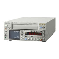
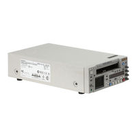
Sony DVCAM DSR-45P Manuals
Manuals and User Guides for Sony DVCAM DSR-45P. We have
3
Sony DVCAM DSR-45P manuals available for free PDF download: Service Manual, Operating Instructions Manual, Pocket Manual
Sony DVCAM DSR-45P Service Manual (305 pages)
DIGITAL VIDEO CASSETTE RECORDER
Brand:
Sony
| Category:
VCR
| Size: 62.63 MB
Table of Contents
Table of Contents
4
Service Note
7
Note for Repair
7
Self-Diagnosis Function
8
Self-Diagnosis Display
8
Service Mode Display
8
Self-Diagnosis Code Table
9
General
10
Features
10
Location and Function of Parts
10
Displaying Various Data
14
Notes on Video Cassettes
15
Playback
16
Recording
18
Notes on Usage in the Editing System
19
Connections for Digital Non-Linear Editing
19
Connections for a Cut Editing System
20
Connections for an A/B Roll Editing System
20
Adjusting Edit Timing
21
Setting the Time Code and User Bits
22
Synchronizing the Time Codes
23
Adjusting the Sync and Subcarrier Phases of the Video Signals
24
Adjusting the Signals
24
Duplication (Generating a Work Tape with the same Time Code)
25
Audio Dubbing
26
Operating the Menus
26
Troubleshooting
31
Alarm Messages
32
Notes on Use
32
Disassembly
33
Upper Case, Bottom Plate
33
Front Panel Block Assembly
33
FR-183/DL-062 Boards
34
LCD Module (LCD901)
34
Mechanism Deck
35
Board
35
JC-21/DI-73 Boards
36
Board
36
Rear Panel Block Assembly
37
Circuit Boards Location-1 (over All)
38
Circuit Boards Location-2 (Mechanism Deck)
39
Block Diagrams
40
Overall Block Diagram 1
40
Overall Block Diagram 2
41
Overall Block Diagram 3
42
Overall Block Diagram 4
43
Overall Block Diagram 5
44
Overall Block Diagram 6
45
Overall Block Diagram 7
46
Overall Block Diagram 8
47
Overall Block Diagram 9
48
Power Block Diagram 1
49
Power Block Diagram 2
50
Power Block Diagram 3
51
Power Block Diagram 4
52
Power Block Diagram 5
53
Printed Wiring Boards and Schematic Diagrams
54
Frame Schematic Diagram (1/2)
56
Schematic Diagrams
57
1/2)(Rec/Pb Amp 1)
57
2/2)(Rec/Pb Amp 2)
58
Vfd(Video Dsp,D/A Converter)
63
9/14) (Mechanism Control 1)
67
10/14) (Mechanism Control 2)
68
11/14) (Mode Control)
69
12/14) (Audio 1)
70
13/14) (Audio 2)
71
14/14) (Power Supply)
72
2/9) (Video Fifo Memory)
74
3/9) (Sync Shifter 1)
75
4/9) (Sync Shifter 2)
76
6/9) (Audio A/D, D/A Converter)
78
8/9) (Audio Dsp Control)
79
9/9) (Time Code In/Out)
81
10/16) (Video out 3)
91
11/16) (Audio)
92
12/16) (Hi Control)
93
13/16) (Rs-232C/422 Control)
94
14/16) (DC In)
95
15/16) (DC/DC Converter 1)
96
16/16) (DC/DC Converter 2)
97
1/3) (DC/DC Converter, Reel Motor Drive)
98
2/3) (Drum Motor Drive, Fl Motor Drive)
99
3/3) (Capstan Motor Drive, Cam Motor Drive)
100
Tape Sensor
101
Ejection Detect Switch
102
Remote Control Receiver
102
Front Door Detect Switch)/Fm-037 (Front Door Motor)
102
User Control
103
Head Phone
104
1/2) (Rgb Driver)
105
2/2) (Timing Generator)
106
Video/Audio In/Out
107
Audio out
108
Rs-422 Driver)/Rs-083 (Rs-232C Driver)
109
DV Connector)/Ls-060 (Control Jack)
109
Acs1581-Ma (Power)
132
Acs1581-Ma
132
Waveforms
133
Parts Location
151
Adjustments
154
Before Starting Adjustment
154
Adjusting Items When Replacing Main Parts and Boards
155
Information (Mechanical Section)
157
Mechanical Section Adjustments
158
Parts Replacement and Preparation for Adjustment
158
Assembly/Disassembly of Cassette Compartment
158
How to Load/Unload
158
List of Service Tools
159
About Mode Selector II
160
Periodic Check
161
Cleaning of Rotary Drum Assembly
161
Cleaning of Tape Path System
161
Periodic Checks
161
Parts Replacement
162
Tape Guide 1/8 and Guide Guard
162
Tape Guide 2/7
162
Capstan Cover
163
Reel Motor
163
FL Motor Assembly, Gear A, Gear B and Gear CD Assembly
163
GL Arm S Assembly, GL Arm T Assembly, Coaster S Assembly and Coaster T Assembly
164
MIC Base Guide, MIC Base Assembly and MIC Base Spring
165
Drum Cap, Drum Assembly and Tape Support
165
Pinch Arm Assembly
166
Capstan Motor
166
Pendulum Retainer and Pendulum Arm Assembly
166
Brake Arm S, Ratchet Brake T
167
Flexible Board (Condensation Sensor)
167
Reel Table Assembly, Idler Gear a Assembly and Idler Gear B
167
Reel Base Retainer, Reel Base T Assembly and Reel Base S Assembly (Reel Lock Release Block and Reel Lock Release Spring)
168
Cam Motor, Motor Holder
168
TG2/7 Arm Block, TG2/7 Band Block and Tension Coil Spring (TG2)/(TG7)
169
Sub-Slider Arm, Sub-Slider, Encoder Gear, Main Cam Gear, Coupling Gear, Sub-Cam Gear, Pinch Slider and Loadeing Arm Assy
170
Main Slider, Main Slider Arm and Pendulum Stopper Assembly
172
Board and Encoder Retainer
173
Components of GL Arm S/T Assembly (GL Arm Assembly, GL Helical Torsion Spring, GL Gear)
174
Components of MIC Base Assembly (FP-104 Flexible Board, MIC Base)
174
Components of Drum Assembly (Motor FPC Assembly, Elastic Connector)
175
Components of Pinch Arm Assembly (Tape Retainer, Compression Coil Spring)
175
Components of TG2/7 Arm Assembly (ET Magnet, Magnet Holder)
175
Check and Adjustment
176
Reel Table Height Check and Adjustment
177
TG1/8 Height Check and Adjustment
177
TG2/7 Height Check and Adjustment
178
FWD/RVS Position Check and Adjustment
178
Electric Tension Regulator Check and Adjustment of TG2/7 Arm
179
FWD/RVS Back Tension Check and Adjustment
180
Preparation for Adjustment and Tape Path Check
181
Track Adjustment and Check (Checking the RF Waveform)
182
Track Check
182
CUE/REV Check
183
Curl Check and Adjustment
183
Rising Check
184
Service Mode
185
Adjusting Remote Commander
185
Used Adjustment Remote Commander
185
Precautions Upon Using the Adjusting Remote Commander
185
Data Processing
186
Service Mode
187
Emergence Memory Address
187
EMG Code (Emergency Code)
187
MSW Code
188
LED Check
191
Switch Check (1)
192
Switch Check (2)
192
Switch Check (3)
192
Switch Check (4)
193
Switch Check (5)
193
Video Section Adjustments
194
Preparations before Adjustment
194
Equipment Used
194
Connection of Equipment
195
Checking the Input Signals
196
S VIDEO Input
196
VIDEO Input
196
COMPONENT Input
197
Adjustment Tapes
198
Input/Output Level and Impedance
199
System Control System Adjustments
200
Initializing the C, D, E
200
Input of C Page Initial Data
200
Input of D Page Initial Data
200
Input of E Page Initial Data
200
Modification of C, D, E
200
Node Unique ID No. Input
201
Servo and RF System Adjustments
206
Capstan FG Adjustment (CM-59 Board)
206
PLL F Pre-Adjustment (RP-234 Board)
206
Switching Position Adjustment (RP-234 Board)
206
RF-AGC Adjustment (RP-234 Board)
206
CLK DELAY and AEQ Adjustment (RP-234 Board)
207
PLL F Final Adjustment (RP-234 Board)
207
Video System Adjustments
207
Board Adjustment
207
VFD SPCK Adjustment (JC-21 Board)
207
A/D Converter Reference Voltage Adjustment (1) (JC-21 Board)
207
A/D Converter Reference Voltage Adjustment (2) (JC-21 Board)
207
Y Signal Clamp Reference Voltage Adjustment (JC-21 Board)
208
CR Signal Clamp Reference Voltage Adjustment (JC-21 Board)
208
CB Signal Clamp Reference Voltage Adjustment (JC-21 Board)
208
AFC Preliminary Adjustment (JC-21 Board)
208
AFC Picture Frame Adjustment (JC-21 Board)
208
AFC Adjustment (JC-21 Board)
208
Playback y Level Adjustment (JC-21 Board)
209
Playback C Level Adjustment (JC-21 Board)
209
General Adjustment
210
Playback Sync Level Adjustment (VD-032 Board)
210
Playback Blanking Level Adjustment with 0% Setup (VD-032 Board)
210
Playback Signal Level Adjustment with 0% Setup
211
(VD-032 Board)
211
Playback CR Signal Level Adjustment with 0% Setup (VD-032 Board)
211
Playback CB Signal Level Adjustment with 0% Setup (VD-032 Board)
212
Playback CR Signal Delay Adjustment (VD-032 Board)
212
Playback CB Signal Delay Adjustment (VD-032 Board)
213
Encoder Free Run Adjustment (VD-032 Board)
213
Carrier Balance Adjustment (VD-032 Board)
214
Burst Level Adjustment (VD-032 Board)
214
Color Level Adjustment with 0% Setup (VD-032 Board)
215
SC_V Phase Adjustment (VD-032 Board)
215
Playback Blanking Level Adjustment with 7.5% Setup (VD-032 Board)(DSR-45)
216
Playback y Signal Level Adjustment with 7.5% Setup (VD-032 Board)(DSR-45)
216
Playback CR Signal Level Adjustment with 7.5% Setup (VD-032 Board)(DSR-45)
217
Playback CB Signal Level Adjustment with 7.5% Setup (VD-032 Board)(DSR-45)
217
Color Level Adjustment with 7.5% Setup (VD-032 Board)(DSR-45)
218
Video Output Level Check (VD-032 Board)
218
S-Video Output Level Check (VD-032 Board)
219
Monitor Terminal Output Level Adjustment (JC-21 Board)
220
E-E Blanking Level Adjustment (VD-032 Board)
221
Component E-E y Signal Level Adjustment (VD-032 Board)
222
Component E-E CR Signal Level Adjustment (VD-032 Board)
222
Component E-E CB Signal Level Adjustment (VD-032 Board)
223
Component E-E CR Signal Delay Adjustment (VD-032 Board)
224
Component E-E CB Signal Delay Adjustment (VD-032 Board)
225
E-E Color Level Adjustment (VD-032 Board)
226
Decoder Free Run Adjustment (VD-032 Board)
227
Decoder HUE Adjustment (VD-032 Board)
228
S Video E-E y Signal Level Adjustment (VD-032 Board)
229
S Video E-E CR Signal Level Adjustment (VD-032 Board)
229
S Video E-E CB Signal Level Adjustment (VD-032 Board)
230
S Video E-E CR Signal Delay Adjustment (VD-032 Board)
231
S Video E-E CB Signal Delay Adjustment (VD-032 Board)
232
Composite E-E y Signal Level Adjustment (VD-032 Board)
233
Composite E-E CR Signal Level Check (VD-032 Board)
233
Composite E-E CB Signal Level Check (VD-032 Board)
234
H Phase Adjustment (VD-032 Board)
235
E-E SC Phase Adjustment (VD-032 Board)
235
Playback SC Phase Adjustment (EXT SYNC OFF) (VD-032 Board)
236
Playback SC Phase Adjustment (EXT SYNC ON) (VD-032 Board)
236
LCD System Adjustments
237
VCO Adjustment (PD-170 Board)
237
D Range Adjustment (PD-170 Board)
238
Bright Adjustment (PD-170 Board)
238
Contrast Adjustment (PD-170 Board)
239
Color Adjustment (PD-170 Board)
239
V-COM Level Adjustment (PD-170 Board)
240
V-COM Adjustment (PD-170 Board)
240
White Balance Adjustment (PD-170 Board)
241
AUDIO System Adjustments
242
Audio PAL Data Input (DSR-45P)
243
Playing Level Check
244
E-E Level Check
244
Frequency Characteristic Check
245
Distortion Check
246
HEAD PHONE Check
247
E-E Maximum Input Check
247
E-E AUTO Check
248
E-E Noise Level Check
248
E-E AUTO Maximum Input Check
249
Time Code System Adjustments
250
Analog through (E-E) Level Check
250
Time Code Reading Check
250
Internal Time Code Output Waveform Check
251
Internal Time Code Output Check
251
Arrangement Diagram for Adjustment Parts
252
Repair Parts List
253
Exploded Views
253
Overall Assembly
253
Front Panel Assembly
254
Rear Panel Assembly
255
Main Frame Assembly
256
CMX Block Assembly
257
Mechanism Deck Assembly (Drum Assembly)
258
Mechanism Deck Assembly (Gear, Arm)
259
Mechanism Deck Assembly (Motor, MD Board)
260
Mechanism Deck Assembly (Cassette Compartment)
261
Electrical Parts List
262
Hardware List
303
Revision History
305
Advertisement
Sony DVCAM DSR-45P Operating Instructions Manual (220 pages)
Digital Videocassette Recorder
Brand:
Sony
| Category:
DVR
| Size: 2.84 MB
Table of Contents
English
6
Table of Contents
6
Chapter 1 Features
9
DVCAM Format
9
Other Features
11
Location and Function of Parts
12
Front Panel
12
Tape Transport Control Section
16
Display Window
19
Rear Panel
20
Supplied Remote Commander
25
Displaying Various Data
27
Chapter 2 Notes on Video Cassettes
30
Inserting/Ejecting Cassettes
31
Notes on Playback/Recording
32
Playback
33
Connections for Playback
33
Settings for Playback
35
Playback Procedures
35
Playback Functions
36
Recording
41
Connections for Recording
41
Settings for Recording
43
Recording Procedures
44
Recording Functions
44
Chapter 3
46
Notes on Usage in the Editing System
46
Connections for Digital Non-Linear Editing
48
Connections for a Cut Editing System
49
Connections for an A/B Roll Editing System
51
Adjusting Edit Timing
56
Chapter 4 Setting the Time Code and User Bits
58
Using the Internal Time Code Generator
58
Synchronizing the Time Codes
62
Connecting to the Time Code Generator
62
Notes on the Time Codes
64
Adjusting the Sync and Subcarrier Phases
66
Adjusting the Signals
68
Chapter 5
69
Audio Dubbing
69
Chapter 6 Operating the Menus
76
Changing the Menu Settings
77
Menu Organization
77
Menu Contents
78
Remote Menu
80
Display Set Menu
85
Audio Set Menu
88
Others Menu
92
Chapter 7
93
Troubleshooting
93
Alarm Messages
97
Notes on Use
98
Notes on the Videocassette Recorder
98
Cleaning of the Video Heads
98
Notes on the Video Cassettes
99
Notes on the LCD Screen
99
About Moisture Condensation
99
Digital Hours Meter
100
Self-Diagnostics Function
100
Appendix Compatibility of DVCAM and DV Format
101
Information
103
Specifications
104
Glossary
106
Index
108
Submenu Index
109
Français
112
Lecture Et Enregistrement
112
Caractéristiques
115
Format DVCAM
115
Autres Caractéristiques
117
Emplacement Et Fonction des Pièces
118
Panneau Avant
118
Panneau Arrière
127
Télécommande Fournie
132
Affichage de Différentes Données
134
Remarques Sur Les Cassettes VIDéo
137
Insertion/Éjection de Cassettes
138
Remarques Sur la Lecture Et L'enregistrement
139
Lecture
141
Raccordements Pour la Lecture
141
Configuration Pour la Lecture
143
Procédures Pour la Lecture
143
Fonctions de Lecture
144
Enregistrement
149
Raccordements Pour L'enregistrement
149
Configuration Pour L'enregistrement
151
Procédures D'enregistrement
152
Fonctions D'enregistrement
152
Remarques Sur L'utilisation Dans un Système de Montage
154
Raccordements du Montage Non Linéaire Numérique
156
Raccordements Pour un Système de Montage de Coupe
157
Raccordements du Système de Montage en Mode A/B
159
Réglage du Temps de Montage
164
Utilisation du Générateur de Code Temporel Interne
166
Synchronisation des Codes Temporels
171
Raccordement Au Générateur de Code Temporel
171
Remarques Sur Les Codes Temporels
173
Réglage des Phases de Synchronisation Et de Sous-Porteuse des Signaux VIDéo
175
Réglage des Signaux
177
Copie (Génération D'une Bande de Travail Avec Le Même Code Temporel)
178
Doublage Audio
183
Utilisation des Menus
185
Organisation des Menus
186
Contenu des Menus
187
Dépannage
202
Messages D'alarmes
206
Remarques Sur L'utilisation
207
Remarques Sur L'enregistreur de Cassettes VIDéo
207
Nettoyage des Têtes VIDéo
208
Remarques Sur Les Cassettes VIDéo
208
A Propos de la Condensation D'humidité
209
Compteur Horaire Numérique
209
Remarques Sur L'écran À Cristaux Liquides
209
Fonction D'autodiagnostics
210
Annexe
211
Compatibilité des Formats DVCAM Et DV
211
Remarques Concernant Les Informations du Rapport
213
D'aspect Grand Écran
213
Spécifications
214
Glossaire
217
Index
219
Sony DVCAM DSR-45P Pocket Manual (10 pages)
Sony Camcorder User Manual
Brand:
Sony
| Category:
Camcorder
| Size: 0.31 MB
Advertisement
Advertisement
Related Products
Sony DSR-450WSL
Sony DSR-450WSPL
Sony DSR-450WS
Sony DSR-450WSP
Sony DSR-400PL
Sony DSR-400K
Sony DSR-400PK
Sony DSR-400L
Sony DSR-400P
Sony DSR-400
Sony Categories
Laptop
TV
CD Player
Camcorder
Digital Camera
More Sony Manuals
Login
Sign In
OR
Sign in with Facebook
Sign in with Google
Upload manual
Upload from disk
Upload from URL