Sign In
Upload
Manuals
Brands
Sony Manuals
CRT TV
KV-34FS120
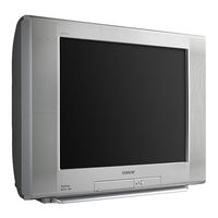
Sony KV-34FS120 Manuals
Manuals and User Guides for Sony KV-34FS120. We have
3
Sony KV-34FS120 manuals available for free PDF download: Service Manual
Sony KV-34FS120 Service Manual (164 pages)
COLOR TELEVISION
Brand:
Sony
| Category:
TV
| Size: 11.4 MB
Table of Contents
Table of Contents
3
Service Manual
1
Section Title
3
Table of Contents
3
Specifi Cations
4
Warnings and Cautions
6
Safety Check-Out
7
Self-Diagnostic Function
8
Section 1: Disassembly
10
Rear Cover Removal
10
Chassis Assembly Removal
10
Service Position
11
Picture Tube Removal
12
Anode Cap Removal Procedure
12
Cable Wire Dressing
13
KV-27FS320/32FS320/36FS320 Models
13
KV-32FS120/34FS120 Models
13
KV-36FS120/38FS120 Models
18
Section 2: Set-Up Adjustments
23
Beam Landing
23
Convergence
24
Focus
25
Screen (G2)
26
Method of Setting the Service Adjustment Mode
26
White Balance Adjustments
26
Section 3: Safety Related Adjustments
27
R530, R531 Confi Rmation Method (HV Hold-Down Confi Rmation) and Readjustments
27
B+ Voltage Confi Rmation and Adjustment
27
Section 4: Circuit Adjustments
28
Setting the Service Adjustment Mode
28
Memory Write Confi Rmation Method
28
Remote Adjustment Buttons and Indicators
28
Service Data Lists
29
KV-27FS320 Service Data
29
KV-32FS320 Service Data
30
KV-36FS320 Service Data
39
KV-32FS120/34FS120 Service Data
48
KV-36FS120/38FS120 Service Data
57
ID Map Table
57
A Board Adjustments
58
Section 5: Diagrams
61
Circuit Boards Location
61
Printed Wiring Board and Schematic Diagram Information
61
Block Diagram and Schematics
62
A Board Schematic Diagram (1 of 2)
63
A Board Schematic Diagram (2 of 2)
64
HM Board Schematic Diagram (1 of 4) (KV-27FS320/32FS320/36FS320 Only)
66
HM Board Schematic Diagram (2 of 4) (KV-27FS320/32FS320/36FS320 Only)
67
HM Board Schematic Diagram (3 of 4) (KV-27FS320/32FS320/36FS320 Only)
68
HM Board Schematic Diagram (4 of 4) (KV-27FS320/32FS320/36FS320 Only)
68
Board Schematic Diagram
69
M Board Schematic Diagram
70
C Board Schematic Diagram
72
HN Board Schematic Diagram (KV-27FS320/32FS320/36FS320 Only)
73
HR Board Schematic Diagram (KV-27FS320/32FS320/36FS320 Only)
73
HS Board Schematic Diagram (KV-32FS120/34FS120/36FS120/38FS120 Only)
73
HU/HD Board Schematic Diagram (KV-27FS320/32FS320/36FS320 Only)
76
Semiconductors
79
Section 6: Exploded Views
80
Chassis
80
Picture Tube (KV-27FS320/32FS320/36FS320 Only)
81
Chassis
82
Picture Tube
83
Section 7: Electrical Parts List
84
Safety Precautions
111
Important Safeguards
112
Replacement Parts
113
Table of Contents
115
Introduction
117
Introducing the FD Trinitron WEGA Features
117
About this Manual
118
Batteries for the Remote Control
118
Front Panel Menu Controls
118
Using the Remote Control Remote Control Description
119
Programming the Remote Control
121
Using Your TV Remote Control with Other Equipment
123
Connecting Your TV
125
TV Rear Panel
125
Basic Connections
126
Connecting Additional Equipment
127
Using Basic Functions
139
Setting up the TV
139
Quick Start to the Menus
140
Using the Menus
143
How to Access Menus
143
Using the Video Menu
144
Using the Audio Menu
145
Using the Channel Setup Menu
147
Using the Parental Control Menu
149
Parental Control
150
Movie Rating
152
United States: Selecting Custom Rating Options
152
Canada: Selecting Custom Rating Options
154
Using the Timer Menu
155
Using the Setup Menu
156
Other Information Troubleshooting
157
Specifications
161
Index
163
Advertisement
Sony KV-34FS120 Service Manual (133 pages)
TRINITRON COLOR TELEVISION
Brand:
Sony
| Category:
TV
| Size: 17.76 MB
Table of Contents
Service Manual
1
Section Title
3
Table of Contents
3
Specifi Cations
4
Warnings and Cautions
6
Safety Check-Out
7
Self-Diagnostic Function
8
Section 1: Disassembly
10
Rear Cover Removal
10
Chassis Assembly Removal
10
Service Position
11
Picture Tube Removal
12
Anode Cap Removal Procedure
12
Cable Wire Dressing
13
KV-27FS320 Models
13
KV-32FS120/34FS120 Models
18
KV-32FS320 Models
20
KV-36FS120/38FS120 Models
25
KV-36FS320 Models
27
Section 2: Set-Up Adjustments
31
Beam Landing
31
Convergence
32
Focus
33
Screen (G2)
34
Method of Setting the Service Adjustment Mode
34
White Balance Adjustments
34
Section 3: Safety Related Adjustments
35
R530, R531 Confi Rmation Method (HV Hold-Down Confi Rmation) and Readjustments
35
B+ Voltage Confi Rmation and Adjustment
35
Section 4: Circuit Adjustments
36
Setting the Service Adjustment Mode
36
Memory Write Confi Rmation Method
36
Remote Adjustment Buttons and Indicators
36
Service Data Lists
37
KV-27FS320 Service Data
37
KV-32FS120/34FS120 Service Data
46
KV-32FS320 Service Data
55
KV-36FS120/38FS120 Service Data
64
KV-36FS320 Service Data
73
ID Map Table
82
A Board Adjustments
83
Section 5: Diagrams
86
Circuit Boards Location
86
Printed Wiring Board and Schematic Diagram Information
86
Block Diagram and Schematics
87
A Board Schematic Diagram (1 of 2)
88
A Board Schematic Diagram (2 of 2)
89
HM Board Schematic Diagram (1 of 4) (KV-27FS320/32FS320/36FS320 Only)
91
HM Board Schematic Diagram (2 of 4) (KV-27FS320/32FS320/36FS320 Only)
92
HM Board Schematic Diagram (3 of 4) (KV-27FS320/32FS320/36FS320 Only)
93
HM Board Schematic Diagram (4 of 4) (KV-27FS320/32FS320/36FS320 Only)
93
Board Schematic Diagram
94
M Board Schematic Diagram
95
C Board Schematic Diagram
97
HN Board Schematic Diagram (KV-27FS320/32FS320/36FS320 Only)
98
HR Board Schematic Diagram (KV-27FS320/32FS320/36FS320 Only)
98
HS Board Schematic Diagram (KV-32FS120/34FS120/36FS120/38FS120 Only)
98
HU/HD Board Schematic Diagram (KV-27FS320/32FS320/36FS320 Only)
101
Semiconductors
104
Section 6: Exploded Views
105
Chassis
105
(KV-27FS320/32FS320/36FS320 Only)
105
Picture Tube (KV-27FS320/32FS320/36FS320 Only)
106
Chassis
107
(KV-32FS120/34FS120/36FS120/38FS120 Only)
107
(KV-32FS120/34FS120/36FS120/38FS120 Only)
108
Section 7: Electrical Parts List
109
Sony KV-34FS120 Service Manual (93 pages)
COLOR TELEVISION
Brand:
Sony
| Category:
CRT TV
| Size: 2.98 MB
Table of Contents
Section Title
2
Table of Contents
2
Specifi Cations
3
Warnings and Cautions
5
Safety Check-Out
6
Self-Diagnostic Function
7
Section 1: Disassembly
9
Rear Cover Removal
9
Chassis Assembly Removal
9
Service Position
10
Picture Tube Removal
11
Anode Cap Removal Procedure
11
Cable Wire Dressing
12
KV-27FS320/32FS320/36FS320 Models
12
KV-32FS120/34FS120 Models
12
KV-36FS120/38FS120 Models
17
Section 2: Set-Up Adjustments
22
Beam Landing
22
Convergence
23
Focus
24
Screen (G2)
25
Method of Setting the Service Adjustment Mode
25
White Balance Adjustments
25
Section 3: Safety Related Adjustments
26
R530, R531 Confi Rmation Method (HV Hold-Down Confi Rmation) and Readjustments
26
B+ Voltage Confi Rmation and Adjustment
26
Section 4: Circuit Adjustments
27
Setting the Service Adjustment Mode
27
Memory Write Confi Rmation Method
27
Remote Adjustment Buttons and Indicators
27
Service Data Lists
28
KV-27FS320 Service Data
28
KV-32FS320 Service Data
29
KV-36FS320 Service Data
38
KV-32FS120/34FS120 Service Data
47
KV-36FS120/38FS120 Service Data
56
ID Map Table
56
A Board Adjustments
57
Section 5: Diagrams
60
Circuit Boards Location
60
Printed Wiring Board and Schematic Diagram Information
60
Block Diagram and Schematics
61
Chassis
61
A Board Schematic Diagram (1 of 2)
62
A Board Schematic Diagram (2 of 2)
63
Picture Tube (KV-27FS320/32FS320/36FS320 Only)
63
HM Board Schematic Diagram (1 of 4) (KV-27FS320/32FS320/36FS320 Only)
65
Chassis
65
HM Board Schematic Diagram (2 of 4) (KV-27FS320/32FS320/36FS320 Only)
66
HM Board Schematic Diagram (3 of 4) (KV-27FS320/32FS320/36FS320 Only)
67
HM Board Schematic Diagram (4 of 4) (KV-27FS320/32FS320/36FS320 Only)
67
Picture Tube
67
Board Schematic Diagram
68
M Board Schematic Diagram
69
C Board Schematic Diagram
71
HN Board Schematic Diagram (KV-27FS320/32FS320/36FS320 Only)
72
HR Board Schematic Diagram (KV-27FS320/32FS320/36FS320 Only)
72
HS Board Schematic Diagram (KV-32FS120/34FS120/36FS120/38FS120 Only)
72
HU/HD Board Schematic Diagram (KV-27FS320/32FS320/36FS320 Only)
75
Semiconductors
78
Section 6: Exploded Views
79
(KV-27FS320/32FS320/36FS320 Only)
79
(KV-32FS120/34FS120/36FS120/38FS120 Only)
81
(KV-32FS120/34FS120/36FS120/38FS120 Only)
82
Section 7: Electrical Parts List
83
Advertisement
Advertisement
Related Products
Sony KV-34XBR800
Sony FD Trinitron WEGA KV-36FS16
Sony KV-36FS70K
Sony FD Trinitron WEGA KV-32FS200
Sony FD Trinitron WEGA KV-32FV300, FD Trinitron WEGA KV-36FV300
Sony KV-36XBR450H
Sony KV-32FQ80U
Sony FD Trinitron KV-32FX68K
Sony WEGA KV-32CS70U
Sony Trinitron KV-32FC60
Sony Categories
Laptop
TV
CD Player
Camcorder
Digital Camera
More Sony Manuals
Login
Sign In
OR
Sign in with Facebook
Sign in with Google
Upload manual
Upload from disk
Upload from URL