Sign In
Upload
Manuals
Brands
Xerox Manuals
Printer
7700DX - Phaser Color Laser Printer
Xerox 7700DX - Phaser Color Laser Printer Manuals
Manuals and User Guides for Xerox 7700DX - Phaser Color Laser Printer. We have
3
Xerox 7700DX - Phaser Color Laser Printer manuals available for free PDF download: Service Manual, Advanced Features And Troubleshooting Manual, User Manual
Xerox 7700DX - Phaser Color Laser Printer Service Manual (406 pages)
Color Laser Printer
Brand:
Xerox
| Category:
Printer
| Size: 12.22 MB
Table of Contents
Table of Contents
13
Service Manual
3
User Safety Summary
5
Terms on Product
5
Power Source
6
Power Supply and Electrical Components
6
Mechanical Components
6
Laser Components
7
Fuser Components
7
Safety Components
7
Warning Labels
7
Safety Instructions
8
Care of Product
8
Ground the Product
8
Service Safety Summary
9
General Guidelines
9
Class 1 Laser Product
9
Federal Communication Commision Compliance
10
Canadian Notice
11
Avis Canadien
11
European Notice
11
Hinweis
11
ESD Precautions
12
Table of Contents
13
Phaser 7700 Finisher 11-313
20
General Information
31
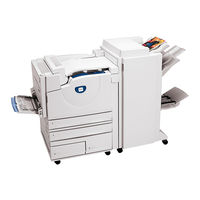
Figure 1-1 the Phaser 7700 Color Laser Printer (Shown with the High-Capacity Feeder)
31
Phaser 7700 Printer Overview
32
Printer RAM and Printer Capabilities
34
CRC Life Counter Behavior
35
Table 1-1 CRC Life
35
Engine Control Interface and Power Supply Boards
36
Figure 1-2 Engine Control Interface and Power Supply Boards
36
Power Supplies
37
Figure 1-3 Power Supplies
37
Engine Control and Image Processor Boards
38
Figure 1-4 Engine Control and Image Processor Boards
38
Auxiliary Feeder Control Board
39
Figure 1-5 Auxiliary Feeder Control Board
39
Print Engine Sensors and Switches
40
Figure 1-6 Print Engine Sensors and Switches
40
Print Engine Sensors and Switches (Cont'D.)
41
Figure 1-7 Print Engine Sensors and Switches (Cont'D.)
41
Auxiliary Feeder Sensors and Switches
42
Figure 1-8 Auxiliary Feeder Sensors and Switches
42
Auxiliary Feeder Actuators and Clutches
43
Figure 1-9 Auxiliary Feeder Actuators and Clutches
43
Print Engine Solenoids, Actuators, and Clutches
44
Figure 1-10 Print Engine Solenoids, Actuators, and Clutches
44
Print Engine and Auxiliary Feeder Interlocks and Sensors
45
Figure 1-11 Print Engine and Auxiliary Feeder Interlocks and Sensors
45
Image Processor Board
46
Figure 1-12 Image Processor Board
46
Assemblies of the Print Engine
47
Figure 1-13 Assemblies of the Print Engine
47
Assemblies of the Print Engine (Cont'D.)
48
Figure 1-14 Assemblies of the Print Engine (Cont'D.)
48
Figure 1-15 Assemblies of the Print Engine (Cont'D.)
49
Auxiliary Feeder Assemblies
50
Figure 1-16 Auxiliary Feeder Assemblies
50
Front Panel Description
51
LED Indicators
51
Table 1-2 Front Panel Key Descriptions
51
Figure 1-17 Front Panel
51
Front Panel Shortcuts
52
Table 1-3 Front Panel Shortcuts
52
Rear Panel
53
Connectors
53
Table 1-4 Rear Panel DIP Switch Settings
53
Figure 1-18 Printer Rear Connections
53
Printer Specifications
54
Physical Dimensions and Clearances
54
Table 1-5 Physical Dimensions of the Printer
54
Table 1-6 Physical Dimensions of Lower Tray Feeder
54
Figure 1-19 Printer Clearances
54
Table 1-7 Functional Specifications
55
Table 1-8 Electrical Specifications
55
Table 1-9 Environmental Specifications
56
Supported Paper Weights, Page Sizes and Print Area
57
Table 1-10 Specialty Paper
58
Table 1-11 Print Area
58
Diagnostics, Error Codes and Messages
61
Error Messages
61
Troubleshooting Error Codes
61
Chain / Link
61
Where Do They Come from
61
Why Are They here
61
System Boot Sequence
62
Power on Self Test (POST)
62
POST Faults
63
Fault Reporting Devices
63
LED Blink Patterns
63
POST Diagnostics Test Descriptions
64
Table 2-1 POST Diagnostics Test Descriptions
64
Service Diagnostics
65
Entering Service Diagnostics Mode
65
Dip Switches
65
Service Diagnostics Test Menu Functions
66
Table 2-2 Service Diagnostics Test Menu Functions
66
Error Codes and Messages Troubleshooting
76
Voltage Measurements
76
Figure 2-1 Voltage Measurement Point Locations
76
Fuser Connector Pin Locations
77
Fig 2-2 Fuser Connector Pin Locations
77
Finisher Wiring Diagrams
114
Wiring Diagrams
114
Troubleshooting
117
Troubleshooting Network Problems
118
Operating System and Application Problems
118
Media Jams and the Paper Path
118
Print Image Quality Problems
118
Troubleshooting Power Supplies and Interlocks
119
Troubleshooting AC Power
119
Troubleshooting the Low-Voltage Power Supplies
119
Troubleshooting the +3.3 VDC and +5 VDC LVPS
120
Troubleshooting the +24 VDC LVPS
120
Interlock Circuit Diagram
121
The +24 VDC Interlock Circuit
121
Figure 3-1 Circuit Diagram
121
The +5 VDC Interlock Circuit
122
Troubleshooting When the Printer Does Not Come to a "Ready" State
123
Printer Does Nothing When Power Switched on
123
Fans On, Front Panel LED Never on
123
Fans On, Front Panel LED Is Red, no Front Panel Message
123
Front Panel Continually Displays the Xerox Phaser 7700 Splash Screen
123
Front Panel Continually Displays "Warming up - Please Wait" Message
123
Front Panel Displays "Fatal Fault Encountered" Message
124
Troubleshooting - Printer Comes to a "Ready" State
124
False LH Door, RH Door, or Front Door Open Messages
124
False "Load Paper in Tray [1,2,3,4]" Message
124
False "Tray [1,2,3,4] Missing" Message
124
Tray 1 will Not Lift
125
Tray 2, 3 or 4 will Not Lift
125
Tray 2, 3 and 4 will Not Lift or Printer will Not Recognize the Auxiliary Feeder
126
Printer will Not Recognize the Finisher
126
Troubleshooting the Toner Dispense/Auger/Developer System
127
Checking the Toner Cartridge
127
Figure 3-2 Toner Cartridge Gear
127
Checking the Toner Auger System
128
Figure 3-3 Toner Cartridge
128
Figure 3-4 Toner Dispense Assembly
129
Figure 3-5 Toner Port
130
Checking the Developer ATC Sensor
131
Checking the Developer
132
Tips
132
Figure 3-6 Developer Housing
133
Operation System and Application Problems
134
Macintosh Printing Problems
134
Windows Printing Problems
134
Troubleshooting Network Problems
135
Media Jams and the Paper Path
136
Media-Based Problems
136
Multiple-Sheet Pick
136
Mis-Pick
136
Skewed Image
136
Damaged Prints
137
Fuser Jams
137
Exit Jams
137
Print Image Quality Problems
138
Light (Undertone) Prints (All Colors)
138
Blank Prints
138
One Color Is Faded or Missing
139
Missing Band in Direction of Paper Travel
140
Streaks in Direction of Paper Travel
141
Streaks Parallel with the Leading Edge
142
Random Missing Spots
143
Random Spotting
143
Single Color
143
All Colors
144
Repetitive Mark Appears on each Print
144
Background Contamination
145
Unfused Image or Image Easily Rubs off of Page
146
Toner on Back of Print
147
Print Is Mottled
148
Image Mis-Registered on Paper
149
Residual Image or Ghosting
150
Light Bands, Dark Bands, or Mottled Prints
151
Adjustments and Calibration
153
Internal Hard Drive
153
Registration Control (Regicon) Adjustment Overview
154
Coarse Regicon Initialization
154
Figure 4-1 Coarse Regicon Initialization
154
Coarse and Fine Skew Adjustments
155
In/Out Skew Adjustment
155
Figure 4-2 Coarse and Fine Skew Adjustments
155
Figure 4-3 In/Out Skew Adjustment
155
Center Skew Adjustment
156
Figure 4-4 Center Skew Adjustment
156
Processes of the Regicon Adjustment
157
Check Print-Quality
157
Preparation for Regicon
157
Registration Control Procedures
160
Regicon Flowchart
163
Figure 4-5 Regicon Flowchart
163
Step 1: Belt Edge Learn
164
Step 2: Regicon #4 Coarse Skew Adjustment
165
Step 3: Regicon #1 Fine Skew Adjustment
167
Step 4: Regicon #2 In/Out Skew Adjustment
168
Step 5: Regicon #3 Center Skew Adjustment
169
Coarse Regicon Initialization
170
Figure 4-6 Grid 1-Dot Pattern Orientation for A-Size Paper
170
Figure 4-7 Grid 1-Dot Pattern Annotations
171
ATC Sensor Setup
172
Additional Information
172
Cleaning and Maintenance
173
Service Preventive Maintenance Procedure
173
Recommended Tools
173
Cleaning
173
Resetting NVRAM
175
Postscript NVRAM Resets
175
Restore Factory Settings (Color)
175
Restore Previous Settings (Color)
175
Restore Factory Settings (Margins)
176
Reset Calibrations (Color, Margins, Paper)
176
Resetting All Printer Default Settings (NVRAM)
176
Resetting Engine NVRAM
176
Resetting Job Defaults
177
Resetting Network Setup Values to Default
177
Resetting Accumulator Belt Life
177
Resetting Belt Cleaner Assembly Life
178
Resetting Transfer Roller Life
178
Service Diagnostics NVRAM Resets
179
Postscript NVRAM Reset
179
Clear Tech Rep Faults
179
Reset CRU Life Counters
179
Reset Engine NVRAM
180
Store Engine NVRAM
180
Removal and Replacement Procedures
181
Table of Contents
182
Figure 7-1 Rear Cover Assembly
184
RRP 1 Rear Cover Assembly
184
Figure 7-2 Right Side Cover Assembly
185
RRP 2 Right Side Cover Assembly
185
Figure 7-3 Top Cover Assembly
186
RRP 3 Top Cover Assembly
186
Figure 7-4 Control Panel Assembly
187
RRP 4 Front Panel Assembly
187
Figure 7-5 Top Rear Power Switch Cover and Left-Hand Rear MID Cover
188
RRP 5 Rear Cover, Top Rear Power Switch Cover and LH Rear MID Cover
188
Figure 7-6 Left-Hand Lower Cover Assembly
190
RRP 6 Left-Hand Lower Cover Assembly
190
Figure 7-7 Front Cover Assembly
191
RRP 7 Front Cover Assembly
191
Figure 7-8 Fuser Front Cover
192
Fuser Front Cover
192
RRP 8 Fuser Front Cover
192
Figure 7-9 Rear Shield
193
RRP 9 Rear Shield
193
Figure 7-10 Rear Shield Bracket
194
Figure 7-11 24 VDC Power Supply Shield
195
RRP 11 24 VDC Power Supply Shield
195
Figure 7-12 MPT Assembly
196
RRP 12 Multi-Purpose Tray (MPT) Assembly
196
Figure 7-13 Multi-Purpose Tray Pick Rollers
197
RRP 13 Multi-Purpose Tray Paper Pick Rollers
197
Figure 7-14 Left-Hand Cover Assembly (Left-Hand Door)
198
RRP 14 Left-Hand Cover Assembly (Left-Hand Door)
198
Figure 7-15 Damper Teeth Alignment
199
Figure 7-16 Duplex Chute
200
RRP 15 Duplex Chute
200
Figure 7-17 Duplex Unit Assembly
201
RRP 16 Duplex Unit Assembly
201
Figure 7-18 Transfer Roller Assembly (2Nd BTR)
202
RRP 17 Transfer Roller Assembly (2Nd BTR)
202
Figure 7-19 Inverter Transport Assembly
203
RRP 18 Duplex Transport Assembly
203
Figure 7-20 Fuser Unit
204
RRP 19 Fuser Unit
204
Figure 7-21 Registration Transport Assembly
205
RRP 20 Registration Transport Assembly
205
Figure 7-22 Shutter Solenoid Assembly
206
RRP 21 Shutter Solenoid Assembly
206
Figure 7-23 Tray 1 Feeder Assembly
207
RRP 22 Tray 1 Feeder Assembly and Paper Lift Motor
207
Figure 7-24 Waste Cartridge, Waste Cartridge Cover and Waste Cartridge Sensor Holder
208
RRP 23 Waste Cartridge Sensor Holder
208
Figure 7-25 Print Cartridge Plate Cover (Plastic)
209
RRP 24 Print Cartridge Plate Cover
209
Figure 7-26 Dispense Assembly
210
RRP 25 Dispense Assembly
210
Figure 7-27 Print Cartridge Plate Assembly
212
RRP 26 Print Cartridge Plate Assembly
212
Figure 7-28 Print Cartridge Plate Assembly (Cont'D.)
213
Figure 7-29 Developer Housing Assembly
215
RRP 27 Developer Housing Assembly
215
Figure 7-30 Developer Housing Assembly Recharge
216
RRP 28 New Developer Housing Assembly Charging
216
Figure 7-31 Toner Dispense Motor Assembly
218
RRP 29 Toner Dispense Motor Assembly
218
Figure 7-32 Steering Drive Assembly
219
RRP 30 Steering Drive Assembly
219
Figure 7-33 Waste Toner Agitator Motor Assembly
220
RRP 31 Waste Toner Agitator Motor Assembly
220
Figure 7-34 Mark-On-Belt Sensor
221
RRP 32 Mark-On-Belt (MOB) Sensor
221
Figure 7-35 Exit Transport Assembly
222
RRP 33 Exit Transport Assembly
222
Figure 7-36 Reconfigured Inverter
223
Figure 7-37 Parts no Longer Installed
223
Figure 7-38 Interlock Actuator and Spacers
224
Figure 7-39 Fuser Fan Assembly
225
RRP 34 Fuser Fan Assembly
225
Figure 7-40 Accumulator Belt Assembly
226
RRP 35 Accumulator Belt Assembly
226
Figure 7-41 Belt Cleaner Assembly
228
RRP 36 Belt Cleaner Assembly
228
Figure 7-42 Waste Auger Assembly
229
RRP 37 Waste Auger Assembly
229
Figure 7-43 Laser Unit Assembly
230
RRP 38 Laser Unit
230
Figure 7-44 Laser Unit Label
231
Figure 7-45 Image Processor Board Assembly
232
RRP 39 Image Processor Board Assembly
232
Figure 7-46 Internal Hard Drive
233
RRP 40 Internal Hard Drive
233
Figure 7-47 Electrical Chassis Assembly
234
RRP 41 Electrical Chassis (Card Cage) Assembly
234
Figure 7-48 Engine Control Board
236
RRP 42 Engine Control Board
236
Figure 7-49 Engine Control Interface Board
237
RRP 43 Engine Control Interface Board
237
Figure 7-50 T1 and T3 High-Voltage Power Supplies
238
RRP 44 T1 and T3 High-Voltage Power Supplies
238
Figure 7-51 3.3 VDC and 5 VDC Low-Voltage Power Supplies
240
RRP 45 3.3 VDC and 5 VDC Low-Voltage Power Supplies and Bracket
240
Figure 7-52 LD Power Relay
241
RRP 46 LD Power Relay
241
Figure 7-53 Low-Voltage Power Supply, Fan and Bracket
242
RRP 47 +24 VDC Low-Voltage Power Supply, Fan and Bracket
242
Figure 7-54 T2 High-Voltage Power Supply
243
RRP 48 T2 High-Voltage Power Supply
243
Figure 7-55 Chassis AC Power Assembly
244
RRP 49 Chassis AC Power Assembly
244
Figure 7-56 Main Drive Assembly
245
RRP 50 Main Drive Assembly
245
Figure 7-57 Accumulator Belt Drive Assembly
247
RRP 51 Accumulator Belt Drive Assembly
247
Figure 7-58 Developer Drive Assembly
248
RRP 52 Developer Drive Assembly
248
Figure 7-59 Print Cartridge Drive Assembly
249
RRP 53 Print Cartridge Drive Assembly
249
Figure 7-60 Tray 1 Paper-Select Switches
250
RRP 54 Tray 1 Paper-Select Switches
250
Figure 7-61 Main Lever, Right-Hand and Left-Hand Jacks
251
RRP 55 Main Lever Assembly Right and Left-Hand Jacks
251
Figure 7-62 Lift Pin Alignment
253
Figure 7-63 Cover Screw Location
253
Figure 7-64 Cover Removed
254
Figure 7-65 Tension Spring Location
254
Figure 7-66 Front and Rear Gears Aligned
254
Figure 7-67 Auxiliary Feeder Covers
255
RRP 56 Auxiliary Feeder Covers
255
Figure 7-68 High-Capacity Feeder (HCF) Cover Assembly
256
RRP 57 Auxiliary Feeder Cover Assembly
256
RRP 58 High-Capacity Feeder (HCF) Tray 3
257
Figure 7-70 High-Capacity Feeder (HCF) Tray 4 and Paper Transport
258
RRP 59 High-Capacity Feeder (HCF) Tray 4 and Paper Transport
258
Figure 7-71 LTD Control or HCF Control Board
259
RRP 60 Auxiliary Feeder Control Boards
259
Figure 7-72 Transport Motor Assembly
260
RRP 61 Auxiliary Feeders Motor Assemblies
260
Figure 7-73 Paper-Select Switches
261
RRP 62 Auxiliary Feeder Paper-Select Switches
261
Figure 7-74 Paper Feed Motor Assembly and Chute (LTA & HCF)
262
RRP 63 Auxiliary Feeder Paper Feed Motor Assembly
262
Figure 7-75 Bracket Assembly, Gear RH & Gear LH (HCF)
263
Bracket Assembly, Left-Hand and Right-Hand Gear (HCF)
263
RRP 64 Bracket Assembly, Left-Hand and Right-Hand Gear (HCF)
263
FRU Parts List
265
Table 8-1 Accumulator Belt Frus List
266
Figure 8-1 Accumulator Belt Frus
266
PL 8-2 Left-Hand Door Frus
267
Figure 8-2 Left-Hand Door Frus
267
Table 8-2 Left-Hand Door Frus List
268
Table 8-3 Media Trays Frus List
269
Figure 8-3 Media Trays Frus
269
Table 8-4 Duplex Unit Frus List
270
Figure 8-4 Duplex Unit Frus
270
Table 8-5 Cover Frus List
271
Figure 8-5 Cover Frus
271
Table 8-6 Cover Frus (Cont'D.) List
272
Figure 8-6 Cover Frus (Cont'D.)
272
Figure 8-7 Cover Frus (Cont'D.)
273
Table 8-7 Covers Frus List (Cont'D.)
274
Figure 8-8 Switch and Sensor Frus
275
Table 8-8 Switch and Sensor Frus List
276
Figure 8-9 Switch and Sensor Frus (Cont'D.)
277
Table 8-9 Switch and Sensor Frus List (Cont'D.)
278
Figure 8-10 Circuit Boards Frus
279
Table 8-10 Circuit Board Frus List
280
PL 8-11 Power Supplies Frus
281
Figure 8-11 Power Supplies Frus
281
Table 8-11 Power Supplies Frus List
282
Figure 8-12 Power Supplies Frus (Cont'D.)
283
Table 8-12 Power Supplies Frus List (Cont'D.)
284
Figure 8-13 Motors/Drivers Frus
285
Table 8-13 Motors / Drivers Frus List
286
Figure 8-14 Electrophotographic Components Frus
287
Table 8-14 Electrophotographic Components Frus List
288
Figure 8-15 Electrophotographic Components Frus (Cont'D.)
289
Table 8-15 Electrophotographic Components Frus List (Cont'D.)
290
PL 8-16 Multi-Purpose Tray Frus
291
Figure 8-16 Multi-Purpose Tray Frus
291
Table 8-16 Multi-Purpose Tray (MPT) Frus List
292
PL 8-17 Paper Feed Frus
293
Figure 8-17 Paper Feed Frus
293
Table 8-17 Paper Feed Frus List
294
Figure 8-18 Paper Feed Frus (Cont'D.)
295
Table 8-18 Paper Feed Frus List (Cont'D.)
296
Table 8-19 Fans Frus List
297
Figure 8-19 Fans Frus
297
PL 8-20 Lift Components Frus
298
Figure 8-20 Lift Components Frus
298
Table 8-20 Lift Components Frus List
299
PL 8-21 Wiring Frus
300
Figure 8-21 Wiring Frus
300
Table 8-21 Wiring Frus List
301
Figure 8-22 Auxiliary Feeder Frus
302
Table 8-22 Auxiliary Feeders Frus List
303
Figure 8-23 Lower Tray Deck (LTD) Frus
304
Table 8-23 Lower Tray Deck (LTD) Frus List
305
Table 8-24 Lower Tray Deck (LTD) Frus List (Cont'D.)
306
Figure 8-24 Lower Tray Deck (LTD) Frus (Cont'D.)
306
Table 8-25 High-Capacity Feeder Frus List
307
Figure 8-25 High-Capacity Feeder Frus
307
Table 8-26 High-Capacity Feeder Frus List (Cont'D.)
308
Figure 8-26 High-Capacity Feeder Frus (Cont'D.)
308
Table 8-27 High-Capacity Feeder Frus List (Cont'D.)
309
Figure 8-27 High-Capacity Feeder Frus (Cont'D.)
309
Table 8-28 High-Capacity Feeder Frus List (Cont'D.)
310
Figure 8-28 High-Capacity Feeder Frus (Cont'D.)
310
Table 8-29 High-Capacity Feeder Frus (Cont'D.)
311
Figure 8-29 High-Capacity Feeder Frus (Cont'D.)
311
Table 8-30 Kits
312
Table 8-31 Manual Packs & Service Manual
313
Supplies and Accessories
314
Table 8-32 Software
314
Table 8-33 Supplies
314
Recommended Service Tools
315
Table 8-34 Accessories
315
Table 8-35 Recommended Tools List
315
Test Prints
317
Analyzing the Test Print
318
Print Color Test Prints
319
Diagnostics Mode
321
Figure 11-1 Phaser 7700 Color Laser Printer with the Finisher Option
343
Finisher Overview
344
General Information
345
Table 11-1 Finisher Specifications
345
Figure 11-2 Dimensions of the Finisher
345
Figure 11-3 Assemblies of the Finisher
347
Figure 11-4 Internal Assemblies of the Finisher
348
Figure 11-5 Horizontal Transport Sensor, Interlock and Switch Locator Map
349
Finisher Sensor, Interlock, and Switch Locator Map
350
Figure 11-6 Finisher Sensor, Interlock, and Switch Locator Map
350
Figure 11-7 Finisher Sensor, Interlock, and Switch Locator
351
Removal and Replacement Procedures
353
Figure 11-8 Horizontal Transport Assembly
354
Figure 11-9 H-Transport Top Open, Front and Rear Covers
355
Horizontal Transport Top Open, Front, and Rear Cover
355
Figure 11-10 Horizontal Transport Entrance Upper Cover
356
Figure 11-11 Horizontal Transport Belts
357
Figure 11-12 H-Tra Entrance and Top Tray Full Sensor
358
Figure 11-13 H-Transport Gate-In Solenoid
359
Gate-In Solenoid Assembly
359
Figure 11-14 Finisher Covers
360
Figure 11-15 Stack Height-Sensor Assembly
362
Figure 11-16 Stacker Paper-Sensor Assembly
363
Figure 11-17 Set Clamp Clutch and Gear
364
Figure 11-18 Eject Roll
365
Eject Roll Assembly
365
Figure 11-19 Finisher Control Board, Bracket, and Shield
366
Figure 11-20 Stacker Motor Assembly
368
Figure 11-21 Paddle Shaft
369
Figure 11-22 Paper Transport Motor
370
Figure 11-23 Cam Bracket Assembly
371
Figure 11-24 Staple Unit Assembly
372
Staple Unit Assembly and Motor
372
Figure 11-25 Compiler Tray
374
Figure 11-26 Finisher Unit Main Assemblies Frus
375
Finisher FRU Parts List
375
Table 11-2 Finisher Unit Main Assemblies Frus List
376
Table 11-3 Finisher Covers Frus List
377
Figure 11-27 Finisher Covers Frus
377
Figure 11-28 Finisher Stand Frus
378
Table 11-4 Finisher Stand Frus List
379
Figure 11-29 Gate Unit Frus
380
Table 11-5 Gate Unit Frus List
381
Table 11-6 Horizontal Transport Assembly Frus List
383
Figure 11-31 Horizontal Transport Assembly Frus (Cont'D.)
384
Table 11-7 Horizontal Transport Assembly Frus List (Cont'D)
385
Figure 11-32 Top Cover and Eject Roll Frus
386
Table 11-8 Top Cover and Eject Roll Frus List
387
Table 11-9 Paper Transport Assembly Frus List
389
Figure 11-34 Paper Transport Assembly Frus (Cont'D.)
390
Table 11-10 Paper Transport Assembly Frus List (Cont'D.)
391
Figure 11-35 Staple Unit Assembly Frus
392
Table 11-11 Staple Unit Assembly Frus List
393
Figure 11-36 Compiler Tray Assembly Frus
394
Table 11-12 Compiler Tray Assembly Frus List
395
Figure 11-37 Stacker Elevator Assembly Frus
396
Table 11-13 Stacker Elevator Assembly Frus List
397
Figure 11-38 Exit Assembly Frus
398
Table 11-14 Exit Assembly Frus List
399
Table 11-15 Electrical Frus List
400
Advertisement
Xerox 7700DX - Phaser Color Laser Printer Advanced Features And Troubleshooting Manual (69 pages)
Xerox Phaser 7700: User Guide
Brand:
Xerox
| Category:
Printer
| Size: 3.84 MB
Table of Contents
Table of Contents
4
Advanced Features
7
Print Quality Modes
8
Print Quality Mode
8
Tekcolor™ Color Corrections
9
I Tekcolor Correction
9
Secure Prints, Proof Prints, and Saved Prints
10
Separation Pages
12
Collating Copies
12
N-Up
13
Booklet Printing
13
N-Up (Multiple Pages on a Single Sheet of Paper)
13
Negative and Mirror Images
14
Scaling
15
Watermarks
15
Image Smoothing
16
Color and Color Sampler Charts
17
Color Sampler Charts
17
Help
17
Printing a Color Sampler Chart from the Printer's Front Panel
18
Printing the Color Sampler Charts with Centreware IS
19
Printing the Colors from an Application
19
Printing the Color Sampler Charts with Utility Files
20
PANTONE Colors
21
Printing PANTONE Colors from the Color Selection Book
21
Printing Printer-Specific PANTONE Colors
21
Installing the PANTONE Color Files
22
Printing the PANTONE Color Chart from a Macintosh
22
Printing the PANTONE Color Chart from a PC
23
Adjusting Color Balance
24
Printing the Color Calibration Tutorial
24
Restore Previous Settings
25
Restore Factory Settings
25
Phaserprint Plug-In for Photoshop
26
Installing the Plug-In
26
Using the Plug-In
26
Fonts
28
Resident Typefaces (Postscript)
28
Resident Typefaces (PCL5C)
31
Downloading Fonts
31
Downloading Fonts from a Macintosh
32
Downloading Fonts from a PC
33
Printing a List of Resident Fonts
33
Printer Management
35
Centreware IS Printer Management Software
35
Usage Profile
36
Email Notification
36
Operational Features
38
The Printer's Startup Page
38
Protected Mode for the Front Panel Menus
39
Sysstart Job Execution
40
Sys/Start Job Execution
40
Front Panel Intensity
40
Front Panel Contrast
40
Intelligent Ready Mode
40
Front Panel Language
41
Automatic Tray Switching
42
Printer Utilities
43
Utility Files on the Printer's CD-ROM
43
Installing the Utility Files on a Macintosh
43
Installing the Utility Files on a PC
43
Utility Files on the Xerox Web Site
44
Downloading Utility Files from a Macintosh
45
Using the Apple Printer Utility to Perform Other Tasks
46
Downloading Utility Files from a PC
47
Downloading Files from Windows 95/Windows 98/Windows Me
47
Downloading Files from Windows Nt/Windows 2000
47
Downloading Files if Your Printer Is Connected to a Novell Netware Network
47
Downloading Files if Your Printer Is Connected to Windows NT
48
Troubleshooting Phaser 7700 Color Printers
50
Getting Help
50
Phasersmart
51
Indicator Light Problems
53
Front Panel Menu
53
Problems with Automatic Two-Sided Printing
54
Problems Printing on Labels
54
Print Quality Problems
56
Calibrate for Paper
58
Printing Problems
58
Preventing Media Jams
60
Calibrate Margins
61
Restore Factory Defaults
61
Phaser 7700 Color Printer
62
Specifications for the Phaser 7700 Color Printer
62
Regulatory Information for Phaser 7700 Color Printers
64
Canadian EMC (Electromagnetic Compatibility) Regulatory Standards
64
Declaration of Conformity
65
FCC Class B Device
66
Xerox 7700DX - Phaser Color Laser Printer User Manual (35 pages)
For color laser printers Phaser 7700; Phaser 7760; Phaser 7750;
Brand:
Xerox
| Category:
Software
| Size: 0.33 MB
Table of Contents
User Guide
1
Table of Contents
3
1 Introduction
5
Phasermatch Software, Version 4.0
5
Phasercal Software, Version 4.0
5
Requirements
6
Installing Phasermatch/Phasercal Software
6
Installing on Macintosh Systems
6
Installing on Windows Systems
7
Next Recommended Reading
7
Typical Uses of Phasermatch Software
7
Calibrating a Printer
7
Creating Custom Tekcolor Corrections
8
Creating New Device Link Profiles
9
Creating ICC Profiles
10
Printing with Custom Tekcolor Corrections
10
Next Recommended Reading
10
Spectrophotometer-Based Calibration
12
Printer Calibration
12
Visual Color Calibration
13
Spectrophotometer Calibration Data File
13
3 Creating Custom Tekcolor Corrections
14
Creating Device Link Profiles
14
Selecting a Phaser Printer Profile
15
Selecting a Target Device Profile
15
Creating Custom Tekcolor Corrections
15
Device Link Profile Options Screen
16
Saving Device Link Profile Screen
16
Sending a Custom Tekcolor Correction to the Printer Screen
16
Printing to a Phaser 7760 or Phaser 7750 Printer
18
Macintosh os X
18
Windows 2000 and Windows XP
19
Printing to a Phaser 7700 Printer
20
Macintosh os X
20
Windows 2000 and Windows XP
21
Editing Custom Tekcolor Corrections Overview
22
Editing Hints
22
Managing Tekcolor Corrections on a Phaser 7760 or Phaser 7750 Printer
25
Managing Tekcolor Corrections on a Phaser 7700 Printer
25
Troubleshooting
26
Macintosh System Requirements
26
Windows System Requirements
26
Spectrophotometer Calibration Data File
26
Additional Information
28
Advertisement
Advertisement
Related Products
Xerox 7700
Xerox 7700DN - Phaser Color Laser Printer
Xerox 7700GX - Phaser Color Laser Printer
Xerox Phaser 7760
Xerox Phaser 7750B
Xerox Phaser 7750DN
Xerox Phaser 7750GX
Xerox 7760DN - Phaser Color Laser Printer
Xerox 7760GX - Phaser Color Laser Printer
Xerox Wide Format 7742
Xerox Categories
Printer
All in One Printer
Copier
Printer Accessories
Scanner
More Xerox Manuals
Login
Sign In
OR
Sign in with Facebook
Sign in with Google
Upload manual
Upload from disk
Upload from URL