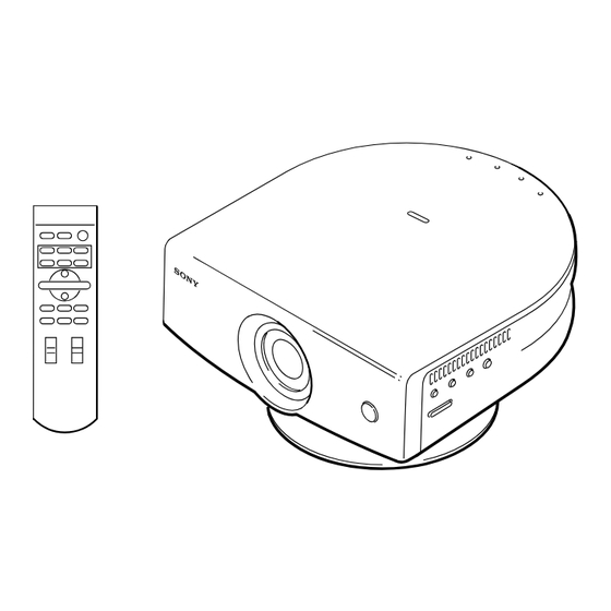
SERVICE MANUAL MODEL MODEL DEST. DEST..........VPL-HS2 RM-PJHS2 WORLD WORLD VPLL-CW20 WORLD SU-HS2 WORLD VPL-HS2 Video Projector VPLL-CW20 Projection Lens (Not Included) SU-HS2 Projector Stand (Not Included) RM-PJHS2 Remote Commander VIDEO PROJECTOR...
Page 2
LES SCHÉMAS DE PRINCIPE, LES VUES EXPLOSÉES ET LES CRITICAL TO SAFE OPERATION. REPLACE THESE COMPO- LISTES DE PIECES SONT D’UNE IMPORTANCE CRITIQUE NENTS WITH SONY PARTS WHOSE PART NUMBERS APPEAR POUR LA SÉCURITÉ DU FONCTIONNEMENT. NE LES AS SHOWN IN THIS MANUAL OR IN SUPPLEMENTS PUB- REMPLACER QUE PAR DES COMPOSANTS SONY DONT LE LISHED BY SONY.
Page 3
Gerät abschaltet und signalisiert “Batterie leer” oder nach längerer Gebrauchsdauer der Batterien “nicht mehr einwandfrei funktioniert”. Um sicherzugehen, kleben Sie die Batteriepole z.B. mit einem Klebestreifen ab oder geben Sie die Batterien einzeln in einen Plastikbeutel. 1 (P) VPL-HS2...
Factory Mode Setting ..............2-1 2-2. V COM Adjustment ..................2-1 2-3. Adjustment Item Initialize Data ..............2-2 2-4. White Balance Adjustment on Servicing ............ 2-8 2-4-1. White Balance Adjustment ............2-8 2-5. Tilt Adjustment ................... 2-8 3. Semiconductors .................. 3-1 VPL-HS2...
Page 6
Schematic Diagrams and Printed Wiring Boards ........6-2 Schematic Diagrams B ........................ 6-3 C ......................6-14 F ......................6-24 G ......................6-26 HA ......................6-29 HB ......................6-30 L ......................6-31 NF ......................6-31 NR ......................6-32 QA ......................6-33 U ......................6-38 VPL-HS2...
Page 7
Printed Wiring Boards B ......................6-12 C ......................6-22 F ......................6-25 G ......................6-28 HA ......................6-29 HB ......................6-30 L ......................6-31 NF ......................6-31 NR ......................6-32 QA ......................6-37 U ......................6-38 VPL-HS2...
2 Open the top cover assy in the direction of the arrow B. 1 Turn the screw of the RE holder assy 3 Remove the top cover assy in the direction of the arrow A. in the direction of the arrow C. VPL-HS2...
Claw Lens 1-2-4. DC Fan Removal To remove the DC fan, remove the Jog unit assy beforehand. 1 Two screws (+B 3x6) 2 Remove the duct (G) in the direction of the arrow. 3 DC fan CN612 C board VPL-HS2...
1 Two screws 2 Remove the blower fan, prism fan holder (+B 3x6) in the direction of the arrow. 7 Blower fan 8 Prism fan holder Connector (3P) 3 Three screws (+B 3x6) 4 Speaker spring assy 5 Speaker Claw VPL-HS2...
G Board Removal 7 Screw (+PSW 3x8) CN708 CN709 CN710 Three claws 0 G holder assy CN601 CN602 !- GL sheet 8 Earth plate (G) != Remove the G board in the direction of the arrow C. 9 CN1 (5P) VPL-HS2...
1 Two screws (+B 3x6) 2 G shield assy, Heat sheet, Sheet G 6 Cap type cover capacitor 4 Two screws (+B 3x6) 7 Remove the F board in the direction of the arrow. 5 AC holder 3 F sheet VPL-HS2...
Filter assy, 4 Jog unit assy Duct (IN) 8 Lamp house 7 Blower fan, Prism fan holder != Remove the QA board in the direction of the arrow. 0 Three screws (+B 3x6) !- Two screws (+M 1.6x5) 1-11 VPL-HS2...
5 SR connector W (4P) 6 ZH connector W (4P) != ZH connector W (12P) 7 SR connector W (5P) Circled numbers on the pages from 1-13 to 1-15 are corresponded to these extension tools. X kit assy (A-1604-234-A) 1-12 VPL-HS2...
There are no need to perform the adjustment. GAIN G GAIN B BIAS R BIAS G BIAS B : When down the data before replacement, and then write in the data after the board replacement. : Need adjustment 1-16 VPL-HS2...
Two times speed Component Component HDTV (YPbPr) HDTV (YPbPr) HDTV (GBR) HDTV (GBR) (Include two times speed) (Include two times speed) High High High Middle Middle Computer Computer Memory Memory Memory Middle Others High Others High Middle Middle 1-17 VPL-HS2...
Page 26
User2 User3 User3 Dynamic Dynamic Standard Standard Cinema Cinema User1 User1 User2 User2 User3 User3 Dynamic Dynamic Standard Standard Cinema Cinema User1 User1 User2 User2 User3 User3 CPU RAM External NVM CPU ROM Memory Initialize Active memory copy 1-18 VPL-HS2...
Cord type SPT-2 H03VVH2-F H03VVH2-F H03VVH2-F VCTFK Rated Voltage & Current 10 A/125 V 2.5 A/250 V 2.5 A/250 V 2.5 A/125 V 7 A/125 V Safety approval UL/CSA DENANHO Cord length (max.) 4.5 m – – – – 1-19 VPL-HS2...
FACTORY MODE? Yes: No: ” will be displayed. 5. Select “Yes: ”. . When leaving the FACTORY MODE, perform item 3. “Do you wish to return to the USER MODE? Yes: No: ” will be displayed. Select “Yes: ”. VPL-HS2...
: “Dot Phase, H Size, Shift H/V and Picture Mode” in the “INPUT SETTING” menu have an initial value respectively in accordance with the input signal (PRESET MEMORY No.). Note : There are nonadjustable items in accordance with the input signal. VPL-HS2...
Page 31
Memory Name Remarks W/B Memory Video Computer High Middle High Middle VPL-HS2...
Page 32
G Osd Lvl B Osd Lvl Through APC Thres APC Limit Note : There are nonadjustable items in accordance with the input signal. : Depends on the color system and the input terminal. : Depend on the input signal. VPL-HS2...
Page 34
Thresh Still Small 22 Pre Post Rate 22 Pre Post Thresh Film Times 22 Ip2/ Sudare Rate 32 Sudare Thresh 32 Sudare Rate 22 Sudare Thresh 22 Note : There are nonadjustable items in accordance with the input signal. VPL-HS2...
Page 35
Adjustment is Adjustment is impossible impossible Adjustment is Adjustment is impossible impossible Adjustment is Adjustment is impossible impossible Adjustment is Adjustment is impossible impossible Adjustment is Adjustment is impossible impossible Adjustment is Adjustment is impossible impossible VPL-HS2...
4. Input the 80 IRE signal to INPUT-A. 5. Adjust the chromaticity (x at 0.313, y at 0.329) values by the GAIN G and B. 6. Repeat above steps 2 to 5 until the chromaticity become the following values. x: 0.313± 0.002, y: 0.329± 0.004 VPL-HS2...
Ne les remplacer que par une pièce portant le numéro spécifié. 2. Standardization of Parts Some repair parts supplied by Sony differ from those used for the unit. These are because of parts common- ality and improvement. Parts List has the present standardized repair parts.
Page 43
X-4039-446-1 s CAP ASSY, LENS 3-715-526-01 o WASHER (M3) (PLA) 4-066-202-01 s SCREW, M3 4-092-444-01 s BUTTON (P) 4-092-499-01 o HOLDER, BUTTON (H) 4-092-512-01 s BUTTON (H) 4-092-436-01 s FILTER, LENS (CINEMA FILTER) 7-682-547-04 s SCREW +B 3X6 7-685-903-21 s SCREW +PWHTP 3X8 VPL-HS2...
Page 45
1-900-271-51 s CONNECTOR ASSY, FLAT 50P 1-763-746-21 s FAN, DC 1-763-757-11 s FAN, BLOWER 4-092-447-01 s PACKING (IN) 4-082-759-01 s SCREW, MACHINE, (+P)M 4X12 7-682-547-04 s SCREW +B 3X6 7-682-948-09 s SCREW +PSW 3X8 7-682-953-09 s SCREW +PSW 3X20 7-682-954-09 s SCREW +PSW 3X25 VPL-HS2...
Page 47
1-468-732-11 s POWER SUPPLY BLOCK (LAMP) 1-763-758-11 s FAN, DC 4-085-052-01 o HOLDER (AC) 4-085-075-01 s SCREW M 1.6X5, SPECIAL HEAD 4-092-446-01 o SHEET, HEAT 4-092-525-01 s STAND 4-092-659-01 o SHEET (GL) 4-374-846-01 o COVER, CAPACITOR, CAP TYPE 7-682-547-04 s SCREW +B 3X6 VPL-HS2...
Page 49
4-082-759-01 s SCREW, MACHINE, +P M 4X12 4-092-417-01 o HOLDER, OUT-POLARIZER 4-092-497-01 o COVER, ZOOM 4-092-498-01 o COVER, FOCUS 4-092-522-01 o BASE, FRAME 4-887-321-01 s SCREW (+B 1.7X4) (G), TAPPING (ST) 7-621-772-10 s SCREW +B 2X4 7-627-552-38 s SCREW +P 1.7X3 VPL-HS2...
Page 51
A-1640-201-A s PS ASSY 4-092-484-01 o FLY EYE, LENS-2 4-092-504-01 o COVER (R), UNIT 4-092-519-01 o COVER (F), UNIT 4-092-520-01 o BASE, UNIT 4-092-720-01 o LENS, B-CH CONDENSER 7-681-000-00 s SCREW +PWH M2X5 7-682-547-04 s SCREW +B 3X6 4-11 VPL-HS2...
1-125-777-11 s CAPACITOR CERAMIC 0.1MF/10V C427 1-107-820-11 s CAPACITOR,CHIP CERAMIC 0.1MF F C428 1-107-820-11 s CAPACITOR,CHIP CERAMIC 0.1MF F C318 1-125-777-11 s CAPACITOR CERAMIC 0.1MF/10V C429 1-107-820-11 s CAPACITOR,CHIP CERAMIC 0.1MF F C430 1-107-820-11 s CAPACITOR,CHIP CERAMIC 0.1MF F 4-13 VPL-HS2...
Page 54
1-107-820-11 s CAPACITOR,CHIP CERAMIC 0.1MF F L152 1-409-529-41 s COIL, CHOKE 10UH C537 1-107-820-11 s CAPACITOR,CHIP CERAMIC 0.1MF F L222 1-469-522-11 s INDUCTOR 1.0UH (NLFV25) C538 1-107-820-11 s CAPACITOR,CHIP CERAMIC 0.1MF F L223 1-469-525-91 s INDUCTOR 10UH (NLFV25) 4-14 VPL-HS2...
Page 55
1-218-990-11 s RESISTOR,CHIP 0 1/16W (1005) R437 1-218-965-11 s RESISTOR, CHIP 10K 1/16W R274 1-218-941-11 s RESISTOR,CHIP 100 1/16W (1005) R438 1-218-965-11 s RESISTOR, CHIP 10K 1/16W R275 1-218-941-11 s RESISTOR,CHIP 100 1/16W (1005) R441 1-208-643-11 s RESISTOR CHIP 22 1/16W (1005) 4-15 VPL-HS2...
Page 56
1-234-372-21 s RES, NETWORK 100X4 (1005) TP505 1-535-757-11 s CHIP, CHECKER (CONNECTOR) RB311 1-234-372-21 s RES, NETWORK 100X4 (1005) X221 1-795-219-21 s VIBRATOR, CRYSTAL RB312 1-234-372-21 s RES, NETWORK 100X4 (1005) RB313 1-234-371-11 s RES, NETWORK 47X4 (1005) 4-16 VPL-HS2...
Page 57
C628 1-119-667-11 s CAPACITOR CERAMIC 22MF/10V(F) C629 1-119-667-11 s CAPACITOR CERAMIC 22MF/10V(F) C630 1-107-820-11 s CAPACITOR,CHIP CERAMIC 0.1MF F C631 1-127-692-11 s CAP, CHIP CERAMIC 10MF B 3216 C632 1-164-506-11 s CAPACITOR,CERAMIC 4.7MF/16V C633 1-126-396-11 s CAPACITOR,ELECT 47MF/16V(CHIP) 4-17 VPL-HS2...
Page 58
CN752 1-794-823-11 s CONNECTOR (ZIF), FPC/FFC 32P C776 1-164-004-11 s CAPACITOR,CERAMIC 0.1MF/25V CN802 1-794-823-11 s CONNECTOR (ZIF), FPC/FFC 32P C777 1-128-992-11 s CAPACITOR ELECT 47MF 25V C778 1-115-339-11 s CAPACITOR,CERAMIC 0.1MF/50V CN852 1-794-823-11 s CONNECTOR (ZIF), FPC/FFC 32P 4-18 VPL-HS2...
Page 59
Q533 6-550-014-01 s TRANSISTOR SSM6N15FU(TE85R) FB756 1-414-921-11 s INDUCTOR, FERRITE BEAD FB757 1-414-921-11 s INDUCTOR, FERRITE BEAD Q534 6-550-014-01 s TRANSISTOR SSM6N15FU(TE85R) FB801 1-414-921-11 s INDUCTOR, FERRITE BEAD Q600 8-729-029-14 s TRANSISTOR DTC144EUA-T106 Q601 8-729-028-91 s TRANSISTOR DTA144EUA-T106 4-19 VPL-HS2...
Page 60
1-218-973-11 s RESISTOR,CHIP 47K 1/16W (1005) R628 1-208-643-11 s RESISTOR CHIP 22 1/16W (1005) R555 1-218-965-11 s RESISTOR, CHIP 10K 1/16W R630 1-218-973-11 s RESISTOR,CHIP 47K 1/16W (1005) R557 1-218-965-11 s RESISTOR, CHIP 10K 1/16W R631 1-218-971-11 s RESISTOR,CHIP 33K 1/16W (1005) 4-20 VPL-HS2...
Page 61
1-218-973-11 s RESISTOR,CHIP 47K 1/16W (1005) R817 1-218-965-11 s RESISTOR, CHIP 10K 1/16W R698 1-218-953-11 s RESISTOR, CHIP 1K 1/16W R821 1-218-990-11 s RESISTOR,CHIP 0 1/16W (1005) R699 1-218-973-11 s RESISTOR,CHIP 47K 1/16W (1005) R822 1-218-990-11 s RESISTOR,CHIP 0 1/16W (1005) 4-21 VPL-HS2...
Page 62
(1005) RB751 1-234-523-21 s RESISTOR,CHIP NETWORK RB801 1-234-523-21 s RESISTOR,CHIP NETWORK RB851 1-234-523-21 s RESISTOR,CHIP NETWORK S701 1-771-337-21 s SWITCH, SLIDE TH521 1-803-382-11 s THERMISTOR (1005) TP521 1-535-757-11 s CHIP, CHECKER (CONNECTOR) TP522 1-535-757-11 s CHIP, CHECKER (CONNECTOR) 4-22 VPL-HS2...
Page 63
8-719-118-12 s DIODE RD33M-B D707 8-719-073-52 s DIODE D2FS6-TA D708 8-719-510-09 s DIODE D10SC6M (RECTI) D709 8-719-073-01 s DIODE MA111-(K8).S0 D710 8-719-073-01 s DIODE MA111-(K8).S0 D712 8-719-510-12 s DIODE D10SC4M D713 8-719-106-23 s DIODE RD7.5M-B2 D714 8-719-106-23 s DIODE RD7.5M-B2 4-23 VPL-HS2...
Page 64
1-216-833-11 s RESISTOR,CHIP 10K 1/10W (1608) R715 1-216-833-11 s RESISTOR,CHIP 10K 1/10W (1608) R717 1-216-833-11 s RESISTOR,CHIP 10K 1/10W (1608) R718 1-202-933-61 s RESISTOR, FUSE 0.1 1/2W R719 1-220-993-91 s RESISTOR,CHIP 0.68 5025 R722 1-216-845-11 s RESISTOR,CHIP 100K 1/10W(1608) 4-24 VPL-HS2...
Page 65
1-218-941-11 s RESISTOR,CHIP 100 1/16W (1005) 1-771-105-11 s SWITCH, TACTILE 1-218-941-11 s RESISTOR,CHIP 100 1/16W (1005) 1-771-105-11 s SWITCH, TACTILE 1-218-941-11 s RESISTOR,CHIP 100 1/16W (1005) 1-218-941-11 s RESISTOR,CHIP 100 1/16W (1005) 1-771-105-11 s SWITCH, TACTILE 1-762-984-11 s SWITCH, PUSH 4-25 VPL-HS2...
Page 66
1-107-826-11 s CAPACITOR,CHIP CERAMIC 0.1MF C314 1-107-826-11 s CAPACITOR,CHIP CERAMIC 0.1MF C315 1-107-826-11 s CAPACITOR,CHIP CERAMIC 0.1MF C316 1-115-339-11 s CAPACITOR,CERAMIC 0.1MF/50V C317 1-126-204-11 s CAPACITOR, ELECT 47MF/16V(CHIP C318 1-126-395-11 s CAPACITOR,ELECT 22MF/16V(CHIP) C319 1-107-826-11 s CAPACITOR,CHIP CERAMIC 0.1MF 4-26 VPL-HS2...
Page 67
1-414-921-11 s INDUCTOR, FERRITE BEAD R105 1-216-864-11 s CONDUCTOR, CHIP (1608) FB304 1-400-150-11 s FERRITE, EMI (SMD) FB305 1-400-150-11 s FERRITE, EMI (SMD) R106 1-216-864-11 s CONDUCTOR, CHIP (1608) R107 1-216-864-11 s CONDUCTOR, CHIP (1608) R108 1-216-864-11 s CONDUCTOR, CHIP (1608) 4-27 VPL-HS2...
Page 68
1-216-821-11 s RESISTOR,CHIP 1.0K 1/10W(1608) R351 1-216-845-11 s RESISTOR,CHIP 100K 1/10W(1608) R229 1-216-805-11 s RESISTOR,CHIP 47 1/10W 1608 R352 1-216-838-11 s RESISTOR CHIP 27K 1/10W(1608) R230 1-216-821-11 s RESISTOR,CHIP 1.0K 1/10W(1608) R353 1-216-838-11 s RESISTOR CHIP 27K 1/10W(1608) 4-28 VPL-HS2...
Page 69
R482 1-218-879-11 s RESISTOR,CHIP 22K 1/10W (1608) RB101 1-234-372-21 s RES, NETWORK 100X4 (1005) TP101 1-535-757-11 s CHIP, CHECKER (CONNECTOR) TP102 1-535-757-11 s CHIP, CHECKER (CONNECTOR) TP301 1-535-757-11 s CHIP, CHECKER (CONNECTOR) TP302 1-535-757-11 s CHIP, CHECKER (CONNECTOR) 4-29 VPL-HS2...
PROT PH701 FEED BACK 6.4V D721 PROT CN709 B16.5V D3.3V IC701 SHUT REG Q707 D3.3V K REF 6.4V 16.5V C BOARD D709 6.4V CN605 6.4V SW IC725 SUB5V BUFF POWER ON GATE PH702 POWER ON Q709 POWER POWER ON VPL-HS2...
Page 101
J L 5 0 1 CN503 J L 5 0 8 J L 5 0 7 FH502 F501 FH501 J L 5 0 6 J L 5 0 3 -B SIDE- -A SIDE- SUFFIX: -11 SUFFIX: -11 6-25 6-25 VPL-HS2...
Page 102
G (1/2) G (1/2) MZ1540 (IC600) BA05FP-E2 (IC724) TL431BCDR2 (IC701) REFFERENCE VOLTAGE Drain Gate Input Source Zero Drain Comparator Cathode Voltage Current Output Sensing Sensing 6-26 6-26 VPL-HS2...
Page 114
S 4 1 CN41 -A SIDE- -B SIDE- SUFFIX: -11 SUFFIX: -11 6-38 6-38 VPL-HS2...
Page 115
2 V AC range are suitable. (See Fig. A) To Exposed Metal Parts on Set 0.15 µF 1.5 k Z voltmeter (0.75V) Earth Ground Fig A. Using an AC voltmeter to check AC leakage. VPL-HS2...